47
6. Commissioning
NOTICE
6.6.3 Tilting the grinding spindle
Risk of damaging the rail!
If the grinding spindle is tilted without the grinding tool being
retracted, a dent will be ground into the rail.
►
Retract the abrasive before adjusting the tilt.
Range +25°/-20°
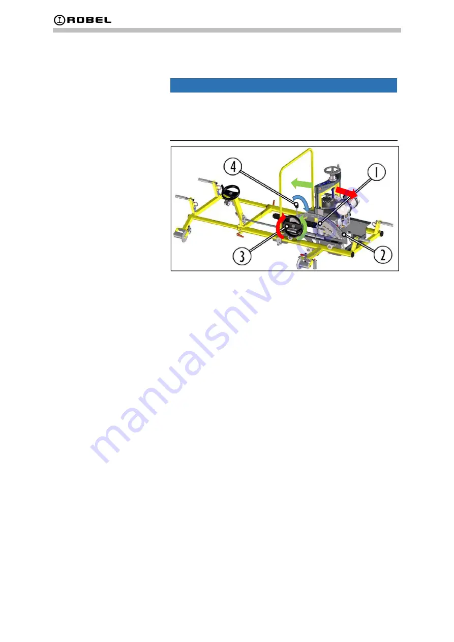
Fig. 42: Tilting the grinding spindle
1
Clamping lever additional angle adjustment
2
Position for up to 80° adjustment distance
3
Handwheel for angle adjustment
4
Ratchet lever
1. Release the ratchet lever (4) (pressing it inwards, blue ar-
row).
Turn the handwheel (3) counter-clockwise (green ar-
rows) to move the spindle axis towards the centre of
the rail.
Turn the handwheel (3) clockwise (green arrows) to
move the spindle axis towards the outside of the rail.
The tilting angle is displayed on a scale.
Adju20°…80°
1. Release the clamping lever (1).
2. Tilt the machine inwards by hand until the position (2) in
the connecting rod is reached.
3. Tighten the clamping lever (1).
The spindle axis can now be adjusted within a range of
approx. 20° to 80°.


