background image

33

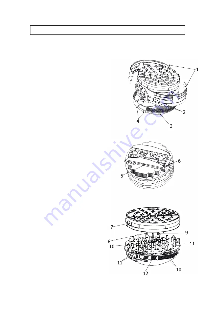
11.1 Removing the optical module


    The following instructions are intended for service purposes only

.

To remove the optical module

1

. Disconnect the fixture from mains.

2

. Loosen the four fastening screws (2) on each  side 

of the head covers (1) to remove the covers.

3

. Loosen the four fastening screws (4) on back cover 

of the head (3)

4

. Unscrew the securing screw (5) with washer from 

the guide-pin. Its position is shown on the picture (the 

fan connecting PCB (6) has to be on the right from 

the securing screw (5)).

If you do not have access to the securing screw, push 

the optical module (7) towards the fans. Do not touch 

the plastic lenses bare hands.

DO NOT FORGET TO UNSCREW THIS SECURING 

SCREW (5)!

5

.  Carefully  take  the  optical  module  (7)  out  of  the 

guide-tubes (11) and motors (10).

To insert the optical module back

1

. Connect the fixture to mains and after fixture reset 

go to tab Manual Control, select item Zoom and set  

it at 255 DMX. 

2

.  Put  the  optical  module  (7)  on  the  LED  module 

(12) in such a way that three guide-pins (8) aim into 

guide-tubes (11) and three lead screws (9) aim into 

motors (10). 

3

. Hold the optical module in this position and slowly 

change the item Zoom from 255 DMX to 0 DMX. 

Motors "draw" the optical module to the LED module 

(12).

DO NOT TRY TO INSERT THE OPTICAL

MODULE BY A FORCE. 

4

. Run the Zoom Reset from tab Manual Control 

or  disconnect/connect the fixture to mains.

5

. Disconnect the fixture from mains.

6

. Screw the securing screw (5) with washer back to 

the guide-pin.

DO  NOT  FORGET TO  SCREW THIS  SECURING 

SCREW (5)!

7

. Screw covers back on the fixture head.  


Summary of Contents for Robin Tarrantula TW

Page 1: ...1 Version 1 3 ...

Page 2: ...tion 10 4 7 Ethernet connection 11 4 8 Wireless DMX operation 13 5 Remotely controllable functions 14 6 Control menu map 15 7 Control menu 18 7 1 Tab Address 19 7 2 Tab Information 20 7 3 Tab Personality 21 7 4 Tab Manual Control 22 7 5 Tab Stand alone 23 7 6 Tab Service 24 8 RDM 26 9 Error and information messages 28 10 Technical Specifications 29 11 Maintenance and cleaning 32 11 1 Removing the ...

Page 3: ...he available voltage is not higher than stated on the rear panel WARNING This unit does not contain an ON OFF switch Always disconnect power input cable to completely remove power from unit when not in use or before cleaning or servicing the unit Make sure that the power cord is never crimped or damaged by sharp edges Check the device and the pow er cord from time to time Always disconnect from th...

Page 4: ... the fixture Always secure the fixture with an appropriate safety wire Only operate the fixture after having checked that the housing is firmly closed and all screws are tightly fastened The maximum ambient temperature 45 C must never be exceeded To avoid damage of an internal optical system of the fixture never let the sunlight or other light source lights directly to the lens array even when the...

Page 5: ...ting the fixture The ENTER DISPLAY ON button also serves for switching the display on when the fixture is disconnected from the mains 1 Lens array Beam shaper 2 Yoke 3 Handle 4 QVGA touch screen 5 Control buttons 6 USB port 7 Tilt lock 8 3 pin DMX OUT 9 Ethernet IN 10 Pan lock 11 Base 12 Ethernet OUT 13 3 pin DMX IN 14 5 pin DMX IN 15 Power 16 Fuse holder 17 5 pin DMX OUT 18 Moving head Robin Tarr...

Page 6: ...ng to the following table Core EU Core US Connection Plug Terminal Marking Brown Black Live L Light blue White Neutral N Yellow Green Green Earth This device falls under class one and must be earthed grounded To apply power first check that tilt and pan lock are released Wiring and connection work must be carried out by qualified staff 4 2 Installing the diffuser 1 Disconnect the fixture from main...

Page 7: ... the beam shaper The following instructions applies to the fixture with installed beam shaper only 1 Disconnect the fixture from mains 2 Loosen the four screws 2 on the beam shaper 1 and carefully remove it from the head 3 When you are installing the beam shaper back on the head the connector on the beam shaper has to be oriented to the connector 3 in the fixture head ...

Page 8: ...ed IMPORTANT OVERHEAD RIGGING REQUIRES EXTENSIVE EXPERIENCE including calculating working load limits installation material being used and periodic safety inspection of all installation material and the projector If you lack these qualifications do not attempt the installation yourself but use a help of professional companies CAUTION Fixtures may cause severe injuries when crashing down If you hav...

Page 9: ...wise 3 Clamp the fixture on a truss 6 and tighten the rigging clamps 4 Pull the safety wire 4 through the attachment point 1 and through the handle 7 and around the truss 6 and lock the snap hook with screw lock gate Use only a safety wire with a snap hook with screw lock gate When installing fixtures side by side avoid illuminating one fixture with another DANGER TO LIFE Before taking into operat...

Page 10: ...nd 5 pin XLR sockets for DMX input and output The sockets are wired in parallel Only use a shielded twisted pair cable designed for RS 485 and 3 pin or 5 pin XLR plugs and connectors in order to connect the controller with the fixture or one fixture with another DMX output DMX input XLR mounting sockets rear view XLR mounting plugs rear view Building a serial DMX chain Connect the DMX output of th...

Page 11: ...3 RX 7 Not connected 4 Not connected 8 Not connected Patch cables that connect fixtures to the hubs or LAN sockets are wired 1 1 that is pins with the same numbers are connected together 1 1 2 2 3 3 4 4 5 5 6 6 7 7 8 8 If only the fixture and the computer are to be interconnected no hubs or other active components are needed A cross cable has to be used 1 3 2 6 3 1 4 8 5 7 6 2 7 5 8 4 If the fixtu...

Page 12: ...onnect the DMX output of this fixture with the input of the next fixture until all fixtures are connected to the DMX chain Caution At the last fixture the DMX chain has to be terminated with a terminator Solder a 120 Ω resistor between Signal and Signal into a XLR plug and connect it in the DMX output of the last fixture Example DMX address 1 DMX address 50 DMX address 200 IP addres 002 168 002 00...

Page 13: ...ill receive DMX value according to this option If DMX input option is set to the wired input this option is saved and checking procedure is finished If DMX input option is not set the fixture continues next 5 seconds in scanning wireless DMX signal see point 2 2 For the next 5 seconds the fixture receives wireless DMX signal and again detects if the Power Special functions channel is set at some D...

Page 14: ...tter unit Smooth 0 100 dimming is provided by the electronic control unit This unit is also used for strobe effects with variable speed Pan Tilt Precise pan tilt movement due to built in electronic motion stabilizer The electronic motion stabilizer ensures precise position of the fixture s head during its movement and reduces its swinging when the truss shakes Pan movement range 540 tilt movement ...

Page 15: ... Priority 0 255 Klingnet Settings Disable Enable Information Fixture Times Power On Time Total Hours Resetable Hours Air Filters Elapsed Time Alert Period 10 300 Fixture Temperatures LEDs Temperature Current Maximum NonRes Maximum Res Base Temperature Current Maximum NonRes Maximum Res DMX Values Pan Dimmer Fine Wireless State Signal Quality Unlink Wireless Adapter Power Channel State Software Ver...

Page 16: ...u t Frequency Standard High LEDs Frequency Adjust 6 0 6 Init Effect Positions Pan 0 255 Dimmer Fine 0 255 Screen Settings Display Intensity 1 10 Screen Saver Delay Off 10min Touchscreen Lock Off 10min Recalibrate Touchscreen Display Orientation Normal Inverted Auto Temperature Unit C F Fan Mode Auto High Date Time Settings Default Settings Manual Control Reset Functions Total System reset Pan Tilt...

Page 17: ... 1 Start Step 1 100 End Step 1 100 Edit Program Steps Step 1 Pan 0 255 Dimmer Fine 0 255 Step Time 0 25 5 sec Step 100 Pan 0 255 Dimmer Fine 0 255 Step Time 0 25 5 sec Service Adjust DMX Values Pan 0 255 Dimmer Fine 0 255 Calibrations Calibrate Effects Pan 0 255 Tilt 0 255 Calibrate Pan Tilt EMS Load Default Calib rations Update Software ...

Page 18: ...sed in the touch screen menu back arrow used to move back to the previous screen menu up arrow used to move up on the previous page down arrow used to move down on the next page confirm used to save adjusted values to leave menu or to perform desired action cancel used to leave menu item without saving changes confirm copy used to save adjusted values and copy them to the next prog step warning ic...

Page 19: ...e cannot be claimed under warranty terms Touch any part of the screen or press the ENTER Display On button to display the initial screen with the cur rent stored DMX address Touch the green arrow at the bottom right corner of the screen or press the ENTER Display On button to enter the Address menu Each item such as a Tab menu item text box icon may be selected from a screen by simply touching the...

Page 20: ...ity The two items of this menu help you to keep cleaning period of the air filters Alert period Cleaning schedule for the fixture depends on the operating environment It is therefore impossible to specify accurate cleaning interval This item allows you to change the cleaning interval of the air filters This alert value is 300 hours and it is set as default Inspect the fixture within its 300 hours ...

Page 21: ...ceived by means of the standard DMX cable Wireless DMX signal is received by means of the inbuilt wireless module Wireless In XLR Out the fixture receives wireless DMX and sends the signal to its wired DMX output The fixture behaves as Wireless Wired adapter The options Wired and Wireless are also stated in DMX chart channel Power Special functions Note If the wireless module is not installed in t...

Page 22: ...t all effects to the desired positions at which they will stay after switching the fixture on without DMX signal connected Screen Settings Use this menu to change the touch screen settings Display Intensity The item allows to control the intensity of the screen 1 min 10 max Screen saver Delay The item allows you to keep the screen on or to turn it off automatically after 1 10 minutes after last to...

Page 23: ...he option starts user program No 3 Play program Use the menu to run desired program in a loop Play Program 1 The option starts user program No 1 Play Program 2 The option starts user program No 2 Play Program 3 The option starts user program No 3 Edit Program Use the menu to create or to edit desired program The Robin Tarrantula TW offers 3 free programs each up to 100 steps Edit Program 1 The opt...

Page 24: ... Default Calibrations The item loads default factory calibration values Update software The menu item allows you to update software in the fixture The following items are required in order to update software PC running Windows or Linux or macOS DSU file Flash cable RS232 DMX P N13050624 or Robe Universal Interface Robe Universal interface WTX To update software in the fixture 1 DSU file is availab...

Page 25: ...n is OK click the Start Uploading button to start software uploading It will take several minutes to perform software update If the option Incremental Update is not checked all processors will be updated including processors with the same software version If you wish to update only processors with new version of software check the Incremental Update box Avoid interrupting the process Update status...

Page 26: ...ard for DMX512 device configuration and status monitoring The RDM protocol allows data packets to be inserted into a DMX512 data stream without adversely affecting existing non RDM equipment By using a special Start Code and by complying with the timing specifications for DMX512 the RDM protocol allows a console or dedicated RDM controller to send commands to and receive messages from specific mov...

Page 27: ...VEL PAN_INVERT TILT_INVERT DEVICE_RESET DMX_PERSONALITY DMX_PERSONALITY_DESCRIPTION STATUS_MESSAGES STATUS_ID_DESCRIPTION DEVICE_HOURS 2 ROBE_DMX_INPUT ROBE_WIRELESS_UNLINK 2 Commands relative resetable values RDM model ID for the Robin Tarrantula TW is 0x0104 ...

Page 28: ... This message will appear after the reset of the fixture if the yoke s magnetic indexing circuit malfunctions sen sor failed or magnet is missing or the stepping motor is defective or its driving IC on the PCB The yoke is not located in the default position after the reset of the fixture Zoom Error 1 Zoom Error 2 The messages will appear after the reset of the zoom module if the zoom module is not...

Page 29: ...ual pan tilt rotation 16 bit movement resolution Pan Tilt electronic motion stabilizer Automatic Pan Tilt position correction Remotely controllable speed of pan tilt movement for easy programming Pan tilt lock mechanism Max pan speed 0 DMX 255DMX 2 9 sec Max tilt speed 0 DMX 255DMX 1 45 sec Removable beam shaper only fixture with beam shaper Beam shaper indexing 0 180 Control Graphic touch screen ...

Page 30: ...io Connection DMX data in out Locking 3 pin and 5 pin XLR AC power IN Neutrik TrueOne NAC3MPX Ethernet IN Out RJ45 Max number of fixtures in Ethernet IN Out line 5 Rigging Mounting points 2 pairs of 1 4 turn locks Mounting horizontally or vertically via two Omega brackets Temperatures Maximum ambient temperature 45 C Maximum housing temperature 75 C Minimum distances Min distance from flammable su...

Page 31: ...r 1x Omega adaptor CL regular 2 pcs in box P N 10980033 1x user manual Optional accessories Diffuser 2 for Robin Tarrantula P N 10980417 Eggcrate for Robin Tarrantula P N 10980431 Upgrade kit CRMX Univerzal 260 P N 99030100 Doughty Trigger Clamp P N 17030386 Safety wire 35 kg P N 99011963 ...

Page 32: ...dry before reapplying power Important Check the air filter periodically and clean before they become clogged Periodically clean air filter placed in the fixture s base The air filter cover is fastened by means of magnets Use a vacuum cleaner compressed air or you can wash them and put back dry After replacing the air filters reset the elapsed time counter in the menu Information Information Air Fi...

Page 33: ...ING SCREW 5 5 Carefully take the optical module 7 out of the guide tubes 11 and motors 10 To insert the optical module back 1 Connect the fixture to mains and after fixture reset go to tab Manual Control select item Zoom and set it at 255 DMX 2 Put the optical module 7 on the LED module 12 in such a way that three guide pins 8 aim into guide tubes 11 and three lead screws 9 aim into motors 10 3 Ho...

Page 34: ...34 11 2 Disposing of the product To preserve the environment please dispose or recycle this product at the end of its life according to the local regulations and codes ...

Page 35: ...35 12 Photometric diagrams without beam shaper ...

Page 36: ...mber 12 2019 Copyright 2016 2019 Robe Lighting All rights reserved All Specifications subject to change without notice Made in CZECH REPUBLIC by ROBE LIGHTING s r o Palackeho 416 20 CZ 75701 Valasske Mezirici ...

Page 37: ...15 19 DMX input Wireless DMX step function is active only 10 seconds after switching the fixture on 20 24 Graphic display On step 25 29 Graphic display Off step 30 39 Reserved 40 44 Pan Tilt speed mode step 45 49 Pan Tilt time mode step 50 54 Blackout while pan tilt moving step 55 59 Disabled blackout while pan tilt moving step 60 64 Dimmer curve square law step 65 69 Dimmer curve linear step 70 7...

Page 38: ... 3 4 White 3800K step 5 6 White 4200K step 7 8 White 4600K step 9 10 White 5000K step 11 12 White 5600K step 13 14 White 6300K step 15 16 White 6500K step 17 255 Warm white Cool white proportional 8 Warm White 8 bit 0 255 Colour saturation control coarse 0 100 255 default proportional 9 Warm White 16bit 0 255 Colour saturation control fine 255 default proportional 10 Cool White 8 bit 0 255 Colour ...

Page 39: ...om fast to slow proportional 160 191 Shutter open step 192 223 Random strobe effect from slow to fast proportional 224 255 Shutter open step 16 Dimmer intensity 8 bit 0 255 Dimmer intensity from 0 to 100 0 default proportional 17 Dimmer intensity fine 16 bit 0 255 Fine dimming 0 default proportional Copyright 2018 2019 Robe Lighting s r o All rights reserved Page 3 ...

Page 40: ...37 ...

Reviews: