background image

REDMix


3•192


19


6.


5


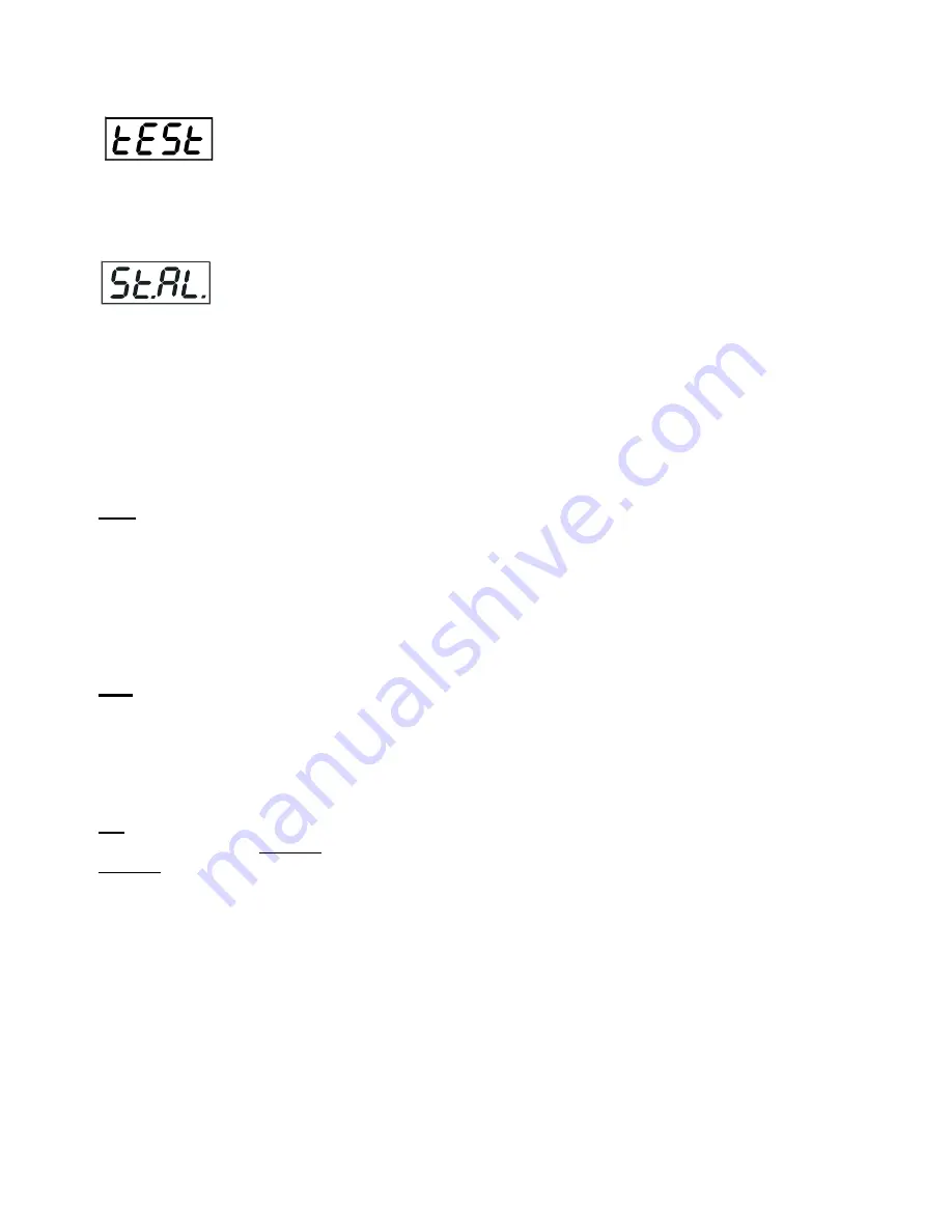
Test


sequences


Use


this


menu


to


run


demo

test


sequences


without


an


external


controller,


which


will


show


you


some


possibilities


of


using


the


REDMix


3•192.


6.6


Stand

­

alone


setting


The


fixtures


on


a


data


link


are


not


connected


to


the


controller


but


can


execute


pre

set


programs


which


can


be


different


for


every


fixture.


“Stand

alone


operation”


can


be


applied


to


the


single


fixture


or


to


multiple


fixtures


operating


synchronously.


Synchronous


operation


of


multiple


fixtures


requires


that


they


must


be


connected


on


a


data


link


and


one


of


them


is


set


as


a


master


(“MASt“)


and


the


rest


as


the


slaves


(“SLA“).


Up


to


32


fixtures


can


be


connected


in


a


master/slave


chain.


Only


one


fixture


can


be


set


as


the


master.


Note:


Disconnect


the


fixtures


from


the


DMX


controller


before


master/slave


operating,


otherwise


data


collisions


can


occur


and


the


fixtures


will


not


work


properly.


See


the


chapters


“Stand

alone


operation“


and


Master/slave


connection“.


Auto.

 ‐‐‐ 

Automatic


playback

.


This


function


allows


you


to


select


the


program


which


will


be


played


after


switching


the


fixture


on.


Selected


program


will


be


played


continuously


in


a


loop.


1.


Use


the


UP/DOWN


buttons


to


find


St.AL.


menu.


2.


Press


the


ENTER


button.


3.


Use


the


UP/DOWN


buttons


to


select


Auto


item.


4.


Press


the


ENTER


button.


5.


Use


the


UP/DOWN


buttons


to


select


desired


program.


6.


Press


the


ENTER


button


to


confirm


the


choice.


PLAY

 ‐‐‐


Playing


program

.


By


enter


to


this


menu


a


complete


overview


of


all


programs


is


offered,


from


which


the


program


to


be


run


can


be


selected.


1.


Use


the


UP/DOWN


buttons


to


find


St.AL.


menu.


2.


Press


the


ENTER


button.


3.


Use


the


UP/DOWN


buttons


to


select


desired


program.


4.


Press


the


ENTER


button.


The


selected


program


runs


in


a


loop.


Edit

 ‐‐‐ 

Editing


a


program

.


The


fixture


offers


3


freely


editable


programs


(EPG.1

EPG.3)


each


up


to


68


steps.


Every


program


step


includes


a


fade


time

the


time


taken


by


the


step´s


channel


status


to


reach


the


desired


level


and


a


step


time

the


total


time


occupied


by


the


step


in


the


program.


E.g.


If


“F.tim.“=5


second


and


“S.tim.“=20


second,


effects


will


go


to


the


desired


position


during


5


seconds


and


after


that


they


will


stay


in


this


position


for


15


seconds


before


going


to


the


next


prog.


step


1.


1.


Use


the


UP/DOWN


buttons


to


find


St.AL.


menu


and


press


the


ENTER


button.


2.


Use


the


UP/DOWN


buttons


to


select


“Edit“


menu


and


press


the


ENTER


button.


3.


Use


the


UP/DOWN


buttons


to


select


a


program


you


want


to


edit


(PrG.1

PrG.3


and


press


ENTER


button.


4.


Use


the


UP/DOWN


buttons


to


select


a


desired


program


step


("St.01"

 ‐ 

"St.68")


and


press


ENTER


button.


5.


Use


the


UP/DOWN


buttons


to


select


a


channel


you


want


to


edit


and


press


the


ENTER


button.


List


of


editable


items:


“P.End”

 ‐


a


total


number


of


the


program


steps


(value


1

68).


This


value


should


be


set


before


start


Programming


(e.g.


if


you


want


to


create


program


with


10


steps,


set


P.End=10).


rEd1”

 ‐ 

rEd4”


a


red


LEDs


saturation


(0

255)


“GrE1“

 ‐ 

“GrE4“


–a


green


LEDs


saturation


(0

255)


“bLu1“

 ‐ 

“bLu4“


a


blue


LEDs


saturation


(0

255)


“Whi1“

 ‐ 

“Whi4“


a


white


LEDs


saturation


(0

255)


Summary of Contents for REDMix 3-192

Page 1: ...Version 1 1 ...

Page 2: ...ion 8 3 6 Stand alone operation 9 4 REDMix 3 192 DMX protocol 10 5 Control menu map 13 6 Fixture menu 15 6 1 Fixture Address 16 6 2 Fixture information 16 6 3 Personality 17 6 4 Manual mode 18 6 5 Test sequences 19 6 6 Stand alone setting 19 6 7 Special functions 20 7 RDM 21 8 Error and information messages 22 9 Technical specifications 23 10 Cleaning and maintenance 25 10 1 Replacing the main fus...

Page 3: ...r authorized distributor or local power company Always disconnect the fixture from AC power before cleaning removing or installing the fuses or any part Make sure that the power switch is set to off position before you connect the fixture to the mains The power plug has to be accessible after installing the fixture Do not overload wall outlets and extension cords as this can result in fire or elec...

Page 4: ...ture Make sure that the area below the installation place is blocked when rigging derigging or servicing the fixture Do not block the front objective LEDs with any object when the fixture is under operation The fixture becomes very hot during operation Allow the fixture to cool approximately 20 minutes prior to manipulate with it Operate the fixture only after having familiarized with its function...

Page 5: ...a stand for placing directly on the stage The mounting bracket consists of two parts and it is designed in a way that no tool is needed to adjust desired fixture position 1 Lens array 2 Mounting bracket 3 Covers 4 Lens array lock 5 Lens array Security locks Rear panel of the fixture 1 Power switch 2 DMX input output 5 pin XLR 3 LED display 4 Mains input 5 Mains output 6 DMX input output 3 pin XLR ...

Page 6: ...ift the security lock 1 to the open position black mark 3 Press and hold the lens module lock 2 on the side cover of the fixture head and gently lift the module 3 upward at the side where this lock is pressed 4 Press and hold the lens module lock 2 on the opposite side of the fixture head and gently lift the lens module 3 from its placing and remove it 5 Fit the new lens module into the fixture he...

Page 7: ...Live L Light blue White Neutral N Yellow Green Green Earth This device falls under class one and must be earthed grounded The REDMix 3 192 allows to connect several fixtures in a daisy chain of power cable Use a 3 conductor 1 5mm2 patch cord for connecting fixtures each other Needed types of the cable connectors are stated in the chapter Technical specifications under section The max number of con...

Page 8: ...irst fixture in the DMX chain 2 Connect the DMX output of the first fixture in the DMX chain with the DMX input of the next fixture 3 Always connect the DMX output with the input of the next fixture until all fixtures are connected Do not overload the link Max 32 fixtures may be connected on a DMX link Caution Terminate the link by installing a termination plug in the output of the last fixture Th...

Page 9: ...ee the Addressing menu A001 Only one fixture can be set as the master The master fixture starts simultaneous program start in the other slave fixtures All fixtures have a definite synchronized starting point when playing back their programs The number of running program is the same in all slaves and depends on the master s choice menu St AL Every fixture runs its program repeatedly starting the pr...

Page 10: ...55 White LEDs Array 1 White LEDs saturation control 0 100 proportional 5 5 9 0 255 Red LEDs Array 2 Red LEDs saturation control 0 100 proportional 6 6 10 0 255 Green LEDs Array 2 Green LEDs saturation control 0 100 proportional 7 7 11 0 255 Blue LEDs Array 2 Blue LEDs saturation control 0 100 proportional 8 8 12 0 255 White LEDs Array 2 White LEDs saturation control 0 100 proportional 9 9 13 0 255...

Page 11: ...7 Macro 8 Macro 9 Macro 10 Macro 11 Macro 12 Macro 13 Macro 14 Macro 15 Macro 16 Macro 17 Macro 18 Macro 19 Macro 20 Macro 21 Macro 22 Macro 23 Macro 24 Macro 25 Macro 26 Macro 27 Macro 28 Macro 29 Macro 30 Macro 31 step step step step step step step step step step step step step step step step step step step step step step step step step step step step step step step 18 17 6 2 0 31 32 63 64 95 96...

Page 12: ...ix 3 192 12 Mode Channel Value Function Type of control 1 2 3 4 5 19 18 7 3 0 255 Dimmer Dimmer intensity from 0 to 100 proportional 20 19 8 4 0 255 Dimmer fine Fine intensity from low to high proportional ...

Page 13: ... Menu Level 3 Menu Level 4 Menu Level 5 Menu Level 6 A001 dM Ad 001 512 MA SL d AbL MASt SLA InFo Poti FuLL totL rSEt EcO totL rSEt FiLt AL PE 10 300 EL ti DM In rEd1 0 255 F dim 0 255 tEMP Cur t boAr LEdS Hi tE boAr LEdS rSEt boAr LEdS VErS IC1 IC2 PErS dM Pr Mod 1 Mod 2 Mod 3 Mod 4 Mod 5 ...

Page 14: ... Level 6 dISP d On On Off d Int 20 100 turn On Off tEM U C F bALA On Off C bAL rEd 0 200 255 GrEn 0 255 bLuE 0 237 255 Stor LOAd FuLL EcO In Po rEd1 0 255 F dim 0 255 Stor dFSE MAn M PrE C rEd1 rE1 1 rE1 3 dimr dim0 dim 7 Man C rEd1 0 255 F dim 0 255 TESt St AL Auto Off tESt PrG 1 PrG 3 ...

Page 15: ...n on its operation test its various parts and lastly program it if it has to be used in a Stand alone mode The four control buttons on the front have the following functions MODE button leaves menu without saving changes ENTER button enters menu confirms adjusted values and leaves menu UP and DOWN buttons move between menu items on the same level sets values After switching the fixture on the fixt...

Page 16: ...tion Use this menu to read useful information about the fixture status To display desired information 1 Use the UP DOWN buttons to find the InFo menu 2 Press the ENTER button 3 Use the UP DOWN buttons to select the required menu item 4 Press the ENTER button to confirm the choice Po ti Power On Time Use the menu item to read the number of operation hours for each LEDs operating mode FuLL Max light...

Page 17: ...side since the REDMix 3 192 has been fabricated rSEt the menu item shows the maximum temperatures of the fixture inside since the counter was last reset In order to reset this counter to 0 you have to press and hold the UP and DOWN buttons and at the same time press the ENTER button Note The ambient temperature should not exceed 40 C Measuring points LEdS the temperature of the LEDs module boAr th...

Page 18: ...s EcO The light output is decreased by 20 The total lumen maintenance is 70 at 60 000 hours In Po Init effect positions Use this function to set all effects to the desired positions to which they will move after switching the fixture on if DMX is not being received dF SE Default Settings The menu item sets all fixture parameters to the default factory values 6 4 Manual mode Use this menu for contr...

Page 19: ...ying program By enter to this menu a complete overview of all programs is offered from which the program to be run can be selected 1 Use the UP DOWN buttons to find St AL menu 2 Press the ENTER button 3 Use the UP DOWN buttons to select desired program 4 Press the ENTER button The selected program runs in a loop Edit Editing a program The fixture offers 3 freely editable programs EPG 1 EPG 3 each ...

Page 20: ...rder to update software PC running Windows 95 98 2000 XP or Linux DMX Software Uploader Flash cable RS232 DMX No 13050624 if you want to use a serial port of PC DreamBox if you want to use an USB port of PC Note1 Software update should execute a qualified person If you lack qualification do not attempt the update yourself and ask for help your ROBE distributor Note 2 DMX address programs 1 3 and a...

Page 21: ... In the case of an interruption of the upload process e g power cut the fixture keeps the updating mode and you have to repeat the software update again For example The fixture was switched off before finishing software upload After switching again the fixture on the fixture is still in the updating mode and the display is dark Restart the Software Uploader program and repeat software update from ...

Page 22: ...OR_VALUE DISPLAY_LEVEL DEVICE_RESET DMX_PERSONALITY DMX_PERSONALITY_DESCRIPTION STATUS_MESSAGES STATUS_ID_DESCRIPTION DEVICE_HOURS Please see the DreamBox user manual for detail description of RDM operation 8 Error and information messages t M Er Temperature measuring error The message informs you that the LED module temperature sensor is defective MA Er Master error The fixture is set as a master...

Page 23: ... digit LED display and four control buttons Control USITT DMX 512 RDM support DMX protocol modes 5 4 8 19 or 20 control channels Control options DMX Auto trigger Operations modes DMX Stand alone Master Slave Manual control of all effects via control panel Strobe Strobe effect with variable speed max 20 flashes per second Pre programmed random strobe pulse effects Dimmer Smooth 16 bit dimming from ...

Page 24: ...x glass holder for frost filter No 10980055 1 x grid module No 17040456 1 x User manual Optional accessories Lens module 45 No 10980053 Lens module 15 x45 No 10980054 Flash cable RS232 DMX No 13050624 Note By reason of the fast moving development of LED technology later products may have better light parameters than previous products ...

Page 25: ... an air jet More complicated maintenance and service operations are only to be carried out by authorized distributors 10 1 Replacing the main fuse Only replace the fuse by the one of the same type and rating To replace the fuse 1 Disconnect the fixture from mains 2 Unscrew the fuse holder on the rear panel of the base with a fitting screwdriver from the housing anti clockwise 3 Remove the old fuse...

Reviews: