background image

MAN F2000

Evolution

Baustufe 12

36

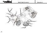
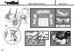
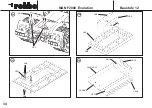
12.16

12.19

12.17

12.15

12.20

12.14

12e

12f

12.18

12.19

12.14-12.18

12.21

12.21

12.22

12.3-12.20

12g

12h

7.2, 12.23

5.10

Summary of Contents for MAN F2000 Evolution

Page 1: ...Montage und Bedienungsanleitung Assembly and operating instructions Notice de montage et d utilisation MAN F2000 Evolution No 3339...

Page 2: ...pare wheel Pressure cast aluminium front axle Rear axle with bevel gear differential Articulated shaft with shaft driver and small items Small parts for RC installation Die cut components for tipper b...

Page 3: ...structions The number before the point indica tes the Stage of construction the number after the point the individual component Directions such as right hand are always as seen from the top rear of th...

Page 4: ...4 MAN F2000 Evolution Baustufe 1 1 3 1 5 1 2 1 6 1 1 1 6 1 7 1 4 L Fahrtrichtung forward sens de la marche...

Page 5: ...e 12 The tipper body 34 37 Stage 1 Initial chassis assembly Part No Description Size mm No off 1 1 Ladder frame 1 1 2 Front leaf spring 2 1 3 Rear R H leaf spring 1 1 4 Rear L H leaf spring 1 1 5 Leaf...

Page 6: ...MAN F2000 Evolution Baustufe 2 6 L 2 9 2 9 2 10 2 11 2 12 2 7 2 3 2 2 2 1 2 4 2 4 2 6 2 5 2 13 2 14 2 13 2 8 2a 2b...

Page 7: ...le de direction 2 x M 2 x 40 1 2 27 vis autotaraudeuse 2 2 x 11 3 2 28 vis t te cylindrique M2 x 10 1 2 29 vis autotaraudeuse 2 2 x 6 5 2 Travaux pr liminaires Appr ter les jantes 2 12 les peindre et...

Page 8: ...5 99 5 mm 65 mm 2 23 2 26 2 23 2 18 2 19 2 21 2 22 2 29 2 22 2 26 2 22 2 20 2 27 2 23 2 24 A A A A 2 27 2 28 2 25 2 5 MA STAB SCALE CHELLE 1 1 2 16 2 17 2 15 1 2 2c 2d 2e 2f MAN F2000 Evolution Baustu...

Page 9: ...ve the servo output disc and fit the lever in its place as shown in the drawing Press the flanged balls 2 24 into the ball links 2 23 2e Screw two ball links 2 23 2 24 on the ends of the trackrod 2 25...

Page 10: ...MAN F2000 Evolution Baustufe 3 10 3 1 3 2 3 6 3 5 3 1 3 4 3 1 3 7 3 3 3 2 3 1 3 3...

Page 11: ...x 5 4 3 19 rondelle ventail 3 2 int r 4 3 20 crou six pans M 3 4 3 21 pneumatique 4 3 22 jante 4 3 23 adaptateur de jante arri re 2 3 24 vis six pans M1 6 x 8 20 3 25 rondelle 8 x 5 x 0 5 2 3 26 goup...

Page 12: ...MAN F2000 Evolution Baustufe 3 12 3 3 3 24 3 22 3 21 3 23 3 27 3 28 3 29 L 3 10 3 12 3 11 3 8 3 9 3 14 3 4 3 15 3 8 3 14 3 13 3 1 3 7 L 3 23 3 17 3 17 3 20 3 19 3 25 1 4 3 26 3 18 3 16 3 14 3a 3b 3c...

Page 13: ...les vis autotaraudeuses 3 13 et 3 14 Enfoncer le capuchon 3 15 Mettre les vis autotaraudeuses 3 14 dans les trous libres des demi axes 3 8 Montage de l essieu arri re n 3 16 3 20 3b visser l essieu ar...

Page 14: ...MAN F2000 Evolution Baustufe 4 14 4 1 1 1 4 2 4 2 4 3 4 4 4 3 4 3 4 4 4 5 4 1 1 1 L 5 mm MA STAB SCALE CHELLE 1 1 4 4 L 4 3...

Page 15: ...1 to the ladder frame 1 1 using the self tapping screws 4 2 Screw a hexagon nut 4 3 onto each of the threaded rods 4 4 keeping to the stated dimension Slip the assemblies 4 3 4 4 through the ladder f...

Page 16: ...5 6 5 5 5 1 3 9 5 3 5 11 5 2 5 4 MAN F2000 Evolution Baustufe 5 16 5 10 5 13 5 12 5 7 100 nF 5 7 100 nF 5 9 47 nF 5 8...

Page 17: ...ach 100 nF capacitor 5 7 to those points Slip a piece of insulating sleeve 5 8 on the other pins and thread the ends through the motor terminals Insulate both pins of the 47 nF capacitor 5 9 and slip...

Page 18: ...4 4 6 2 6 5 6 6 6 7 6 8 4 4 6 5 6 9 6 10 R rechte Seite Right hand side droite L linke Seite Left hand side gauche Rand schwarz lackieren paint the edge black peindre le bord en noir 6 12 6 9 6 11 6...

Page 19: ...covers 6 6 6 8 into the rear light clusters 6 5 and secure them with a little cyano Glue the rear lights 6 5 6 8 in the rear light holders 6 9 Take care to make up two mirror image rear light clusters...

Page 20: ...MAN F2000 Evolution Baustufe 7 20 5 6 2 19 7 1 7 1 7 2 2 19 5 10 5 10...

Page 21: ...te freely and the steered wheels can move to their full travel Check the steering neutral position and travel in both directions Check the neutral position and direction of rotation of the rear wheels...

Page 22: ...MAN F2000 Evolution Baustufe 8 22 8 1 8 2 8 4 8 7 8 8 8 9 8 10 8 3 8 5 8 6 8 10 1 1...

Page 23: ...the steps 8 17 8 22 paint them and allow to dry Glue the step housings 8 15 and 8 16 to the bumper 8 14 using the template S page 43 to fit Trial fit the headlight housings 8 23 and the lamp len ses 8...

Page 24: ...9 8 16 8 20 8 22 8 14 8 14 8 27 8 29 8 17 8 20 8 21 8 22 8 23 8 23 8 25 8 24 8 25 8 26 8 18 8 19 8 16 L rechte Seite R Right hand side droite linke Seite L Left hand side gauche 8 26 8 7 8 8 8 3 8 13...

Page 25: ...d 8 25 into the headlight housings 8 23 and secure them with a little cyano Remove the metallised coating from the headlight housings 8 23 before gluing them in place Remove the metallised coating fro...

Page 26: ...F2000 Evolution Baustufe 9 26 9a 9b 3 mm 9c 9d 9e 9g 9 12 9 1 9 2 9 3 9 4 9 5 1 1 7 1 9 16 9 15 c a 4 0 m m 9f 9 13 9 1 9 2 9 6 9 7 9 9 9 11 9 10 9 8 9 9 9 6 9 9 9 7 9 10 9 11 9 14 9 13 9 14 9 15 9 12...

Page 27: ...de l int rieur Retirer la peinture des emplacements o est appliqu e la colle Coller la calandre 9 10 sur la cabine 9c Selon les indications du sch ma marquer dans la cabine la position des porte carr...

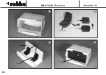
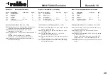
Page 28: ...10 3 10 5 10 5 10 4 MAN F2000 Evolution Baustufe 10 28 10 3 10 5 10 6 10 7 10 1 10 3 10 5 10 2 10 8 10 8 10 8 10a 10 2 10b 10c 10d 10 8 10 8...

Page 29: ...N I Internal driver s cab fittings parts 10 1 10 8 10a Place the window insert 10 1 in the driver s cab and secure it with a little glue 10b Glue the seats 10 3 and the backrests 10 4 to the seat fitt...

Page 30: ...MAN F2000 Evolution Baustufe 11 30 7 1 10 2 11 4 11c 11a 11b 11d 7 1 11 1 10 2 11 1 11 2 11 3 11 5...

Page 31: ...ping screw 1 3 x 4 2 Decal sheet 1 RC installation part 11 1 11a Connect the steering servo 2 19 and the speed control ler 5 10 to the receiver 7 1 11b Fix the receiver 7 1 under the cockpit insert 10...

Page 32: ...7 11 6 11 8 11 10 11 10 11 9 11 9 11 11 11 12 11 13 11 13 11 14 11 8 11 9 11 10 rechte Seite R Right hand side droite linke Seite L Left hand side gauche 11g 11h 11i 11f 11 11 11 12 11 15 11e 11 8 11...

Page 33: ...rear view mirror assemblies 11 8 11 12 paint it and allow to dry 11h Attach the rear view mirror assemblies to the painted mirror holders 11 13 and plug them into the driver s cab Glue them in place...

Page 34: ...MAN F2000 Evolution Baustufe 12 34 12 1 12 6 12 3 12 10 12 2 12a 12b 12d 12 5 12 4 12 11 12 7 12 8 12c 12 3 12 9 12 10 12 11 12 9 12 13 12 5 12 12...

Page 35: ...tape 1 N I Constructing the tipper body Separate all the machined parts from the milled panels and remove all rough edges Use cyano acrylate glue cyano for all joints When joining the parts check con...

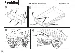
Page 36: ...MAN F2000 Evolution Baustufe 12 36 12 16 12 19 12 17 12 15 12 20 12 14 12e 12f 12 18 12 19 12 14 12 18 12 21 12 21 12 22 12 3 12 20 12g 12h 7 2 12 23 5 10...

Page 37: ...side panels to set the correct spacing but don t glue it in place The tipper body and rear panel can now be painted Mount the completed rear panel between the side panels using the screws 12 19 and nu...

Page 38: ...batterie nearly flat you could lose control of the model You can always tell when the drive batterie is almost discharged because the full throttle running speed will fall off markedly As soon as you...

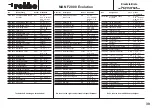
Page 39: ...t moteur 1 4 2 4 5 3350 0014 ressort lame avant 2 kits 1 2 1 5 1 7 2 15 2 17 3350 0015 ressort lame arri re 2 kits 1 3 1 7 3 16 3 20 3350 0016 demi arbre d essieu 2 3 3 3 25 3 26 3350 0017 cardan 1 5...

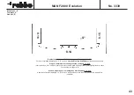
Page 40: ...No 3339 40 MAN F2000 Evolution 12 3 12 12 12 4 Zeichnung 0 Fr steile Drawing 0 machined parts Croquis 0 pi ces frais es...

Page 41: ...MAN F2000 Evolution 41 Zeichnung 0 Fr steile Drawing 0 machined parts Croquis 0 pi ces frais es 12 11 12 10 12 14 12 5 12 15 12 6 12 11 12 6 12 10 No 3339 12 13...

Page 42: ...42...

Page 43: ...ting the step casings 8 15 8 16 Invert parts 8 14 8 15 and 8 16 place them onto the template and adjust them before gluing them in place if necessary trim them to fit Stade 8 Gabarit pour le montage d...

Page 44: ...robbe Modellsport GmbH Co KG Metzloser Str 36 D 36355 Grebenhain Telefon 06644 870 Telefax 06644 74 12 http www robbe com robbe Form 40 4759 EAB...

Reviews: