


Rhein-Nadel Automation GmbH
6
VT-BA-ESR-ESM3000-EN_2020 / 07.05.2020 SJ
2.
Function
The unit is set up by using the touch panel on the front plate (buttons and LED display). All settings can be made by
using the touch panel and a series of menus. The various parameters can be selected by entering operator codes. A
fuller description of the parameters can be found In the section on settings. Alternatively, the feeder throughput can
adjusted by using an external potentiometer, an external voltage signal 0...10 V, DC or a current signal 0(4)...20 mA (the
chosen option must be selected in menu 003). A relay with potential free contacts is provided for feeder status indication
and this operates in conjunction with the feeder enable signal. Terminals for these contacts can be found inside the
controller.
During normal operation the set point is displayed as a percentage in the LED window. In the programming mode the
selected dimension, as described in the setting up instructions, is shown. Changed settings can be stored by leaving
the programming mode or automatically saved by not pressing a key for a period of 100 seconds.
The con
trol units can provide a frequency range from 5…300 Hz, which can be limited by adjustable, upper and lower
frequency limits. The usable adjustment range cannot exceed a ratio of 1:4, i.e. the upper frequency limit cannot be
more than four times the lower frequency limit. It is possible to have a narrower setting of the limits and this provides a
margin of safety against too wide a difference in the vibrating frequency.
The maximum output current drawn by the coil can be determined by integrated current limiting.
Critical parameters such as the current limit and vibrating frequency range are held under a special service menu. This
menu cannot be accessed through the normal menu structure and an additional code number has to be used to gain
access. This prevents unauthorised adjustment of these sensitive parameters.
An interface option can be used to provide an RS232 or Fieldbus (Profibus-DP) connection.
2.1.
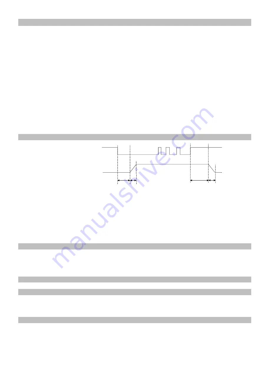
Track control
The output can be switched
ON and OFF from a track
component sensor, using
internal, adjustable time
delays (ton and toff).
The queue of components
rises above and drops
below the track sensor
position.
The
controller
output switches on when
the sensor cannot detect product and a switch-on time delay has elapsed. The output is switched off when product is
detected and a switch-off time delay has elapsed (FULL displayed in the LED window). Gaps in the product feed cause
resetting of the time delay. The time will always be precise from the last or first component, respectively. The ON and
OFF time delays are set in the programming menu. The first decimal point in the display blinks to indicate that an internal
timer is running.
An addition
al “
Sensor-Time-out
timer is started when the feeder switches on. This can be set (30...240 sec.) to switch
off the feeder if no product is sensed in the time out period. The status relay indicates that the feeder is not running and
the LED window displays ERROR and SE alternately. This function is optional and must be selected in the Track Settings
Menu with function EE = 1.
2.2.
Operating with two speeds (2 set points for coarse/fine switching)
Coarse/Fine control can be used instead of track control (Menu C 003). The second set point is activated through the
same sensor input that is used for track control. Either contacts or a 24 VDC signal can be used to change the set point
from coarse to fine. The second set point is activated, immediately, by applying a 24 V signal
(
The track control function is invalid
)
2.3.
Control inputs and output
2.3.1. Enable input
External switch or 24 VDC signal voltage.
External control function to switch the power output ON or OFF e.g. Networking of several controllers from a central
PLC.
2.3.2. Sensor input for track control
Sensor for monitoring the queue of components on the track or an input for switching to the second set point 24 VDC
(PNP).
t ON
t OFF
Sensor
Feeder
ON
OFF
ON
OFF
Soft Start
Soft Stop


