4
H
H
a
a
r
r
d
d
w
w
a
a
r
r
e
e
I
I
n
n
s
s
t
t
a
a
l
l
l
l
a
a
t
t
i
i
o
o
n
n
a
a
n
n
d
d
S
S
e
e
t
t
u
u
p
p
Connection Ports
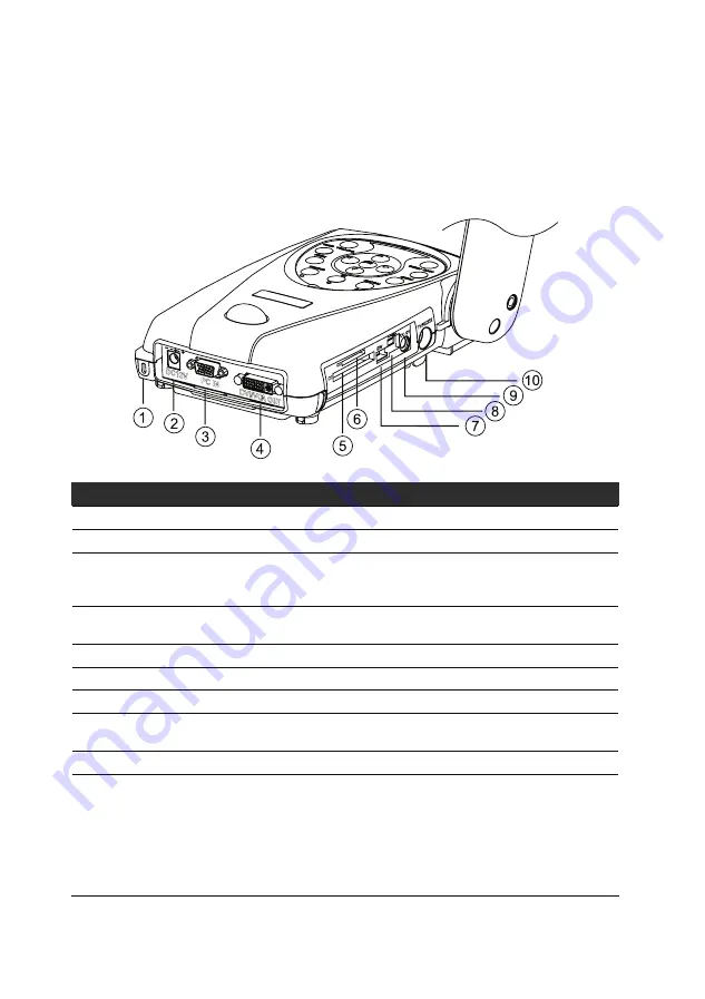
The ports on the back and side panel of the RM Eye are for connecting the unit to a
computer, graphics display monitor or LCD/ DLP projector, TV and other devices.
Illustrated below are the ports that are located at the back and side panel of the RM
Eye with their corresponding labels.
DC12V
PC IN
DVI/VGA O
UT
TV/
RS2
32
DC
6V
SW
SD
CF
Port
Description
1. Security Slot
Connect a Kensington compatible security lock to this slot.
2. DC 12 V (input)
Plug the power adapter in to this Port.
3. PC IN Port
Connect the RM Eye to the VGA output port of the computer. This
enables you to input computer video signal and pass it through to
the DVI/VGA out port.
4. DVI/VGA OUT
Connect it to a VGA/ Mac monitor, LCD/DLP projector, or high-end
projector with DVI interface to display your presentation.
5. CF Card Slot
Insert the CF card with the label facing up.
6. SD Card Slot
Insert the SD card with the label facing up.
7. DIP Switch
Allows you to set the DIP switch configuration settings.
8. USB Port
This port enables you to use RM Eye as a card reader/writer or PC
web cam.
9. DC 6V (output)
Plug the light module or the optional light box in to this port.
10. TV/RS-232
Connect the Mini Din 9-Pin to S-Video/ Composite/ RS-232
Adapter to this port.
The s-video and composite connectors enable you to output your
video camera or preview a picture from a memory card on your TV.
Note: The RS-232 adapter allows you to control the RM Eye using
a computer through an RS-232 connection. Refer to the RS-232
control instructions on your CD for more information.
Summary of Contents for RM Eye
Page 1: ...RM RM Eye User Manual Digital Document Camera...
Page 2: ...P N 300AACEN Made in Taiwan...
Page 6: ......


