background image

Summary of Contents for 2PS-H-N2

Page 1: ...S H N2 2PS H50 N2 2PS HH N2 Rix Industries 2 Stage Oil Less Air Cooled Nitrogen Compressor This manual including information and products referenced herein to be provided by Seller Products are subjec...

Page 2: ...update B 8 19 11 CJC Content update C 5 19 21 ICB Major formatting and content update see ECO 010962 D 7 12 2021 ICB Parts List See ECO 011049 E 10 4 21 AV Parts List Fig 12 See ECO 011231 F 10 26 21...

Page 3: ...er 4 Control System 6 4 1 System Overview 6 4 2 Manual Operation Mode 6 4 3 Auto Operation Mode 6 4 4 Control logic Description 7 4 5 Safety Device Set Points 7 Chapter 5 Routine Inspection Scheduled...

Page 4: ...RIX Industries MAN 2PS2B N2 Page iii 7 8 Main Bearings 17 7 9 Piston to Head Clearance 17 7 10 Clearances Tolerances 18 7 11 Connecting Rod Bearings 19 Appendix 20...

Page 5: ...sor Model Family 2PS2B N2 Serial Number Note Parts recommended for routine service are indicated in the parts lists The customer is advised to maintain these parts at their facility or procure them in...

Page 6: ...this equipment shall be installed and grounded in accordance with applicable codes and regulations 3 Before working on electrical equipment take steps to ensure system is de energized and will remain...

Page 7: ...ion Seller shall at its option either repair or replace its part at the original F O B point of delivery Defective items must be held for Seller s inspection and returned to the original F O B point u...

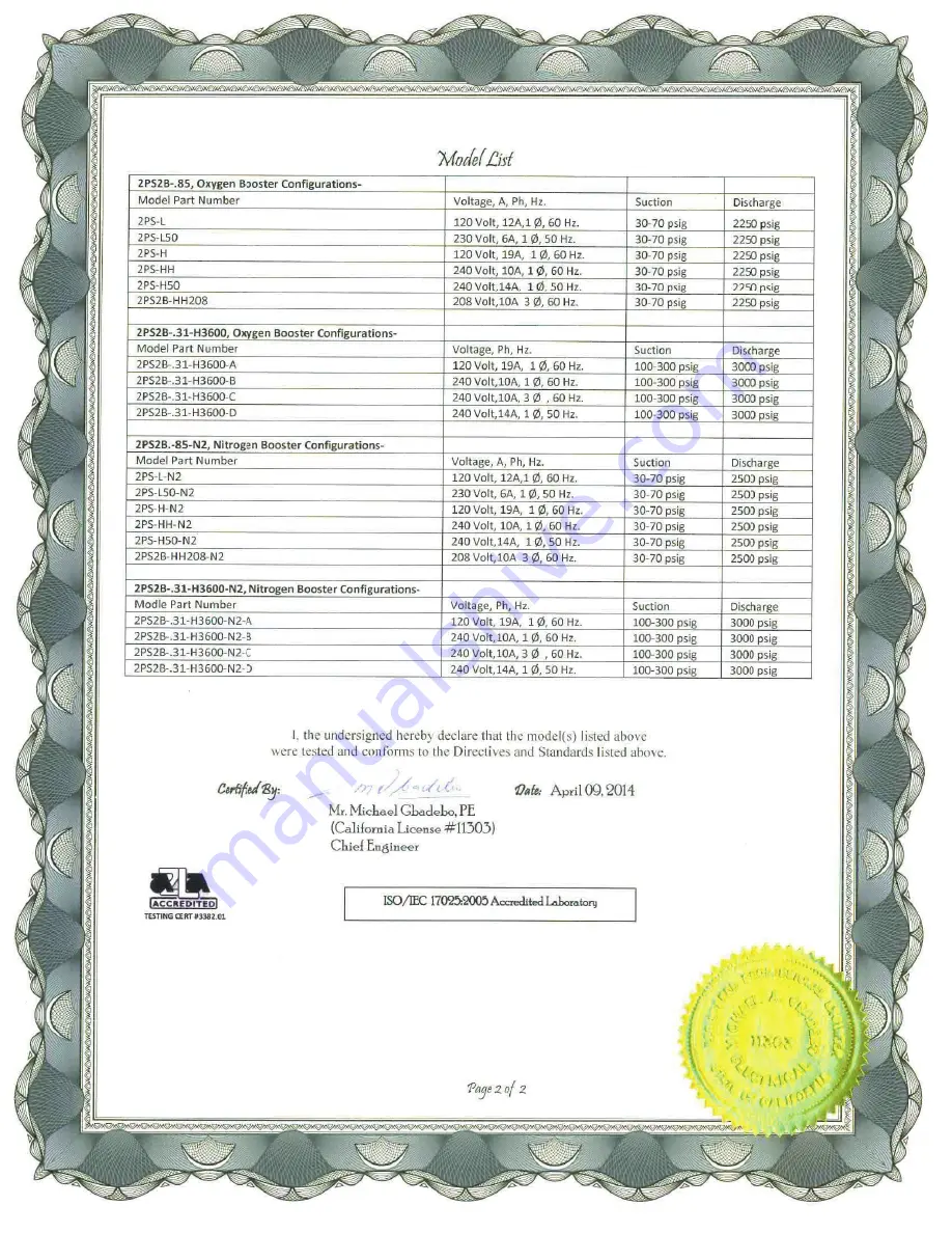
Page 8: ...1PH 60HZ 2PS L50 220VAC 1PH 50HZ 2PS H 115VAC 1PH 60HZ 2PS H50 220VAC 1PH 50HZ 2PS HH 230VAC 1PH 60HZ Gas Input Gas to be compressed Nitrogen clean and dry Suction Pressure Range 30 to 70 psig Suctio...

Page 9: ...energy is released in an uncontrolled manner individuals may be crushed or struck by moving machinery equipment or other items If maintenance is attempted on a pressured line without isolating the lin...

Page 10: ...1 5 Crankcase Lubrication This oil less compressor utilizes sealed bearings Oil less compressors contain absolutely no oil within the whole compressor package removing the likelihood of any oil carry...

Page 11: ...ompressor vibration CAUTION If flexible lines are used user is responsible to secure those lines to prevent whipping in case of breakage Safety relief valves are installed on the compressor at each st...

Page 12: ...e If the compressor is taken out of service provision should be made to protect against corrosion At a minimum gas suction and discharge lines should be capped and belt tension relieved The compressor...

Page 13: ...ression ratio of each stage All shutdown devices and control logic should be tested before the system is put into autonomous operation 3 3 Normal Operating Conditions The table below shows theoretical...

Page 14: ...n both suction and discharge pressure A HOA Hand Off Auto switch is located on the front of the control box and allows operator choice of modes A remote contact is installed in the control box and can...

Page 15: ...tion or discharge switch will break current to the coil TDR which will stop the drive motor 4 The compressor may also be run in the automatic mode by selecting AUTO on the HOA switch All features are...

Page 16: ...ng air flow Verify cooling fans blow air over the heads 4 Inspect for loose fittings or components Fix any issues that are found 5 Inspect for unusual noises or vibrations 5 3 Scheduled Maintenance Se...

Page 17: ...rings expanders and riders should be replaced As the compression rings wear their ability to seal is diminished Excessive wear will result in lower compressor capacity more frequent compressor operati...

Page 18: ...g needs to be replaced If the Wrist Pin outer diameter contains dents or bumps replace both the Wrist Pin and Needle Bearing To inspect the Ball Bearing larger rotate the inner race of the bearing by...

Page 19: ...ssor Specifications Lack of back pressure in user s downstream piping If downstream should be pressurized look for leaks in downstream system If downstream should not be pressurized no problem Restric...

Page 20: ...essure to range stated in Compressor Specifications Fans are inoperative Repair or replace fans High ambient temperature Ensure ambient temperature is within design limits Compressor valves have faile...

Page 21: ...pressor is allowed to cool then restarted immediately prior to conducting the leak test hot components can boil away the soap solution making detection of leaks difficult or impossible Observe for the...

Page 22: ...nish To remove and disassemble both the 1st and 2nd stage compressor valves follow the instructions below 1 Remove the head per Section 7 3 and move to a flat clean surface 2 Separate all components a...

Page 23: ...e 1 Remove the head per Section 7 3 2 Rotate the flywheel to position the 1st stage piston at bottom dead center 3 Slide 1st stage cylinder off piston using caution to prevent side loading the piston...

Page 24: ...on at top dead center 3 Remove hex screw on bearing plate 4 Gently slide assembly outward by pulling connecting rod off crankshaft allowing neck of piston to pass through slot in crankcase Move assemb...

Page 25: ...o the crankcase Heating may be required 3 Install outboard bearing flywheel side 4 Install new lock washer with bearing nut torque to 50 ft lbs and bend lock washer tab to secure nut 5 Reinstall pisto...

Page 26: ...achieve a piston to cylinder clearance of 012 to 016 4 Reinstall the head per Section 7 3 7 10 Clearances Tolerances Part Nominal Dimension Wear Limit 1st Stage Piston to Valve clearance 011 015 Adjus...

Page 27: ...e other which may require a press The piston may also require heating to allow the wrist pin to be removed 4 Remove the connecting rod from the piston assembly 5 Remove the retaining plate from the ba...

Page 28: ...2PS2B N2 Page 20 Appendix 1 Compressor Parts List 2 Figure 1 Compressor Cross Section Fastener Detail 3 Figure 2 Compressor Cross Section Pump Detail 4 Figure 3 1st Stage Valve Detail 5 Figure 4 2nd...

Page 29: ...Cooling Fan Sub Assembly Detail 12 Figure 11 Belt Installation Detail 13 Figure 12 Guard Mounting Detail 14 Figure 13 Control Box Detail 1 of 2 15 Figure 14 Control Box Detail 2 of 2 16 Figure 15 Cont...

Page 30: ...FLAT SAE 17 18 C1791 10R1 2 EACH RING PISTON 1 1 4 DIA 2 18 123 313 5 2 EACH O RING 2 19 18 B2117 2R1 2 EACH RING RIDER 1 1 4 DIA 2 20 54P 4P50NSS 2 EACH PLUG ST THD HEX HEAD 21 123 904 3 2 EACH O RI...

Page 31: ...515 855 1 EACH RELIEF VALVE 56 74 401 3 EACH GAUGE SNUBBER 57 54P 1 4CDSS 3 EACH PIPE ELBOW STREET 58 X60 824 1 EACH GAUGE PRESSURE 59 X60 826 1 EACH GAUGE PRESSURE 60 X60 828 1 EACH GAUGE PRESSURE 61...

Page 32: ...NG 91 40 B5871 1 4 EACH BRACKET 92 40 B5871 2 EACH BRACKET 93 32 1056 4 EACH BOLT SOCKET HEAD 94 53 4087 4 EACH NUT LOCK 95 55 D2621 2 1 EACH LINE INLET PR GAUGE 96 55 D2621 4 1 EACH LINE 1ST STG INLE...

Page 33: ...R QUANTITY DESCRIPTION COMPRESSOR PARTS LIST CONTINUED REF FIGURES 1 12 131 SEE OPTIONS 2 EACH FAN 132 041116 01 1 EACH ELECTRICAL BOX 133 32 22809 4 EACH BOLT SHCS 1 4 20 5 8 L 134 20 12877 4 EACH WA...

Page 34: ...489 1 EACH 2PS L N2 107 1035 1 EACH 2PS L50 N2 107 1035 1 EACH FAN OPTION POSITION NUMBER 131 2PS H N2 42 112 1 EACH 2PS H50 N2 42 113 1 EACH 2PS HH N2 42 113 1 EACH 2PS L N2 42 112 1 EACH 2PS L50 N2...

Page 35: ...10 041116 410 1 EACH PUSHBUTTON MOM BLK FLUSH 411 041116 411 1 EACH LEGEND PLATE HAND OFF AUTO 412 041116 412 1 EACH SELECTOR SWITCH HEAD 3 POS 413 041116 413 1 EACH NC CONTACT BLOCK 414 041116 414 1...

Page 36: ...RIX Industries MAN 2PS2B N2 Page 28 FIGURE 1 COMPRESSOR CROSS SECTION FASTENER DETAIL...

Page 37: ...RIX Industries MAN 2PS2B N2 Page 29 FIGURE 2 COMPRESSOR CROSS SECTION PUMP DETAIL...

Page 38: ...RIX Industries MAN 2PS2B N2 Page 30 FIGURE 3 1ST STAGE VALVE DETAIL...

Page 39: ...RIX Industries MAN 2PS2B N2 Page 31 FIGURE 4 2ND STAGE VALVE DETAIL...

Page 40: ...RIX Industries MAN 2PS2B N2 Page 32 FIGURE 5 EXTERIOR FASTENER DETAIL...

Page 41: ...RIX Industries MAN 2PS2B N2 Page 33 FIGURE 6 MOTOR AND CONTROL BOX MOUNTING...

Page 42: ...RIX Industries MAN 2PS2B N2 Page 34 FIGURE 7 SUCTION PLUMBING DETAIL...

Page 43: ...RIX Industries MAN 2PS2B N2 Page 35 FIGURE 8 INTERSTAGE PLUMBING DETAIL...

Page 44: ...RIX Industries MAN 2PS2B N2 Page 36 FIGURE 9 FINAL DISCHARGE PLUMBING DETAIL...

Page 45: ...RIX Industries MAN 2PS2B N2 Page 37 FIGURE 10 COOLING FAN SUB ASSEMBLY DETAIL...

Page 46: ...RIX Industries MAN 2PS2B N2 Page 38 FIGURE 11 BELT INSTALLATION DETAIL...

Page 47: ...RIX Industries MAN 2PS2B N2 Page 39 FIGURE 12 GUARD MOUNTING DETAIL...

Page 48: ...RIX Industries MAN 2PS2B N2 Page 40 FIGURE 13 CONTROL BOX DETAIL 1 OF 2...

Page 49: ...RIX Industries MAN 2PS2B N2 Page 41 FIGURE 14 CONTROL BOX DETAIL 2 OF 2...

Page 50: ...RIX Industries MAN 2PS2B N2 Page 42 FIGURE 15 CONTROL BOX WIRING DIAGRAM...

Page 51: ...RIX Industries MAN 2PS2B N2 Page 43 FIGURE 16 ELECTRICAL SCHEMATIC...

Page 52: ...RIX Industries MAN 2PS2B N2 Page 44 FIGURE 17 FLOW SCHEMATIC...

Page 53: ...1 7A 2PS H N2 N2 115V 60HZ 1PH 60 SCFH 19A 2PS HH N2 N2 230V 60HZ 1PH 60 SCFH 8 9A 2PS H50 N2 N2 220V 50HZ 1PH 60 SCFH 10A 2PS2B HH208 N2 N2 208V 60HZ 3PH 60 SCFH 5 5A BELTGUARD REMOVED FOR CLARITY 3...

Page 54: ...ture grease such as Krytox or Christo Lube MGC 111 before installation Apply a thin coating by drawing the o ring through your fingers This will extend the life of the seal and simplify installation C...

Page 55: ...justment screw If the set point is on decreasing pressure then increase the pressure vacuum of the source starting at a point higher than the set point Step 3 Using the continuity tester and the press...

Page 56: ......

Page 57: ......

Page 58: ......

Page 59: ......

Reviews: