RIX Industries
MAN-2PS2B-N2
Page 11
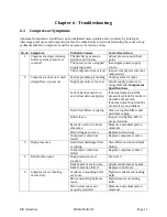
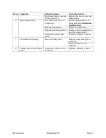
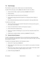
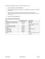
Chapter 6 - Troubleshooting
6.1
Compressor Symptoms
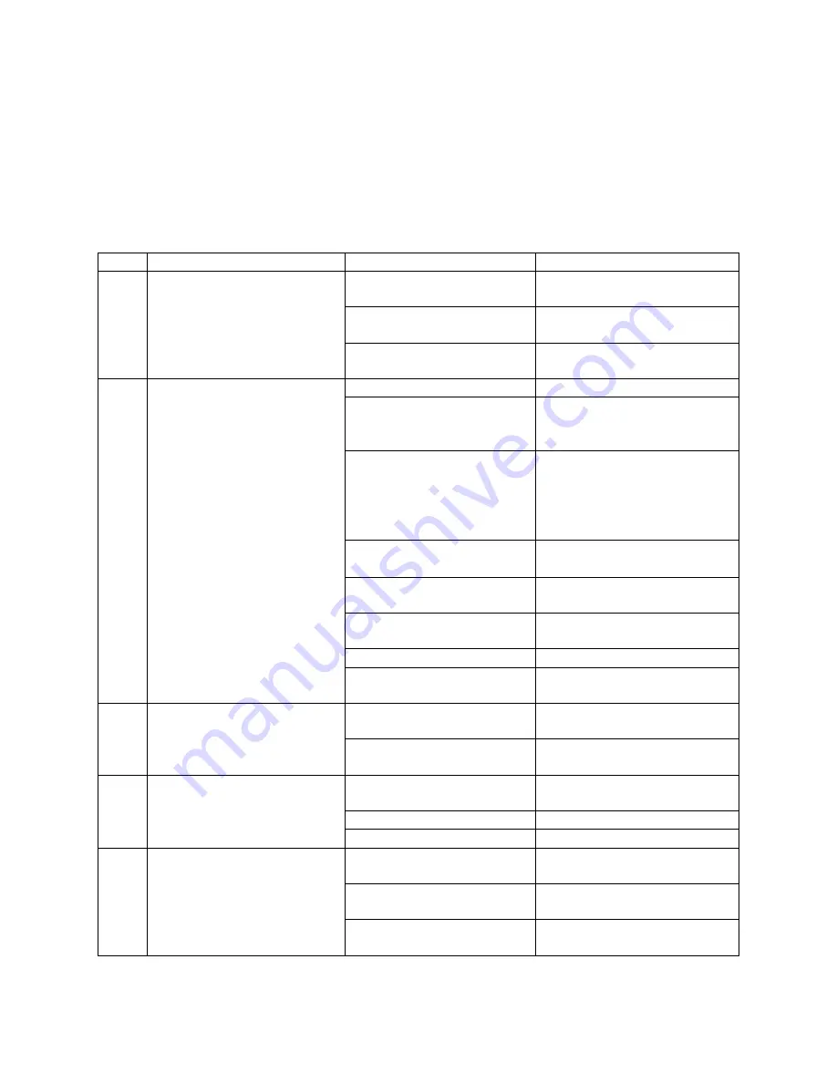
Abnormal compressor conditions can be evaluated more quickly and accurately by looking at
interstage pressures and temperatures. Use the table below to aid in determining the cause of any
problems with the compressor and the necessary corrective action.
Item Symptom
Probable Causes
Corrective Action
1
Compressor stops running
before system pressure is
reached
The discharge pressure
switch is set too low
Adjust pressure switch set
point
The power source stopped
supplying power
Investigate power supply
source
The compressor has seized Inspect compressor internal
components
2
Compressor does not reach
design flow or pressure
System plumbing is leaking Check system for leaks
Supply pressure is too low Adjust supply pressure to
range stated in
Compressor
Specifications
Lack of back pressure in
user’s downstream piping
If downstream should be
pressurized, look for leaks in
downstream system.
If downstream should not be
pressurized, no problem.
Restricted filters or piping Clean or replace filters and
upstream piping
Belt is loose
Inspect and tighten belt to
proper tension
Excessive piston to head
clearance
Measure and adjust piston
clearance
Piston rings are worn
Replace piston rings
Compressor valve has
failed
Replace compressor valve
3
High pressures
Restricted discharge filter
or piping
Clean filter and downstream
piping
Compressor valve has
failed
Replace compressor valve
4
Relief valve opens
High pressures were
reached
See item 3
Relief valve is set too low
Adjust relief valve set point
Relief valve has failed
Replace relief valve
5
Compressor is vibrating
excessively
Crankcase mounting bolts
are loose
Tighten crankcase mounting
bolts
Motor mounting bolts are
loose
Tighten motor mounting
bolts
Piston clearances not
properly adjusted
Measure and adjust piston
clearance
Summary of Contents for 2PS-H-N2
Page 36: ...RIX Industries MAN 2PS2B N2 Page 28 FIGURE 1 COMPRESSOR CROSS SECTION FASTENER DETAIL...
Page 37: ...RIX Industries MAN 2PS2B N2 Page 29 FIGURE 2 COMPRESSOR CROSS SECTION PUMP DETAIL...
Page 38: ...RIX Industries MAN 2PS2B N2 Page 30 FIGURE 3 1ST STAGE VALVE DETAIL...
Page 39: ...RIX Industries MAN 2PS2B N2 Page 31 FIGURE 4 2ND STAGE VALVE DETAIL...
Page 40: ...RIX Industries MAN 2PS2B N2 Page 32 FIGURE 5 EXTERIOR FASTENER DETAIL...
Page 41: ...RIX Industries MAN 2PS2B N2 Page 33 FIGURE 6 MOTOR AND CONTROL BOX MOUNTING...
Page 42: ...RIX Industries MAN 2PS2B N2 Page 34 FIGURE 7 SUCTION PLUMBING DETAIL...
Page 43: ...RIX Industries MAN 2PS2B N2 Page 35 FIGURE 8 INTERSTAGE PLUMBING DETAIL...
Page 44: ...RIX Industries MAN 2PS2B N2 Page 36 FIGURE 9 FINAL DISCHARGE PLUMBING DETAIL...
Page 45: ...RIX Industries MAN 2PS2B N2 Page 37 FIGURE 10 COOLING FAN SUB ASSEMBLY DETAIL...
Page 46: ...RIX Industries MAN 2PS2B N2 Page 38 FIGURE 11 BELT INSTALLATION DETAIL...
Page 47: ...RIX Industries MAN 2PS2B N2 Page 39 FIGURE 12 GUARD MOUNTING DETAIL...
Page 48: ...RIX Industries MAN 2PS2B N2 Page 40 FIGURE 13 CONTROL BOX DETAIL 1 OF 2...
Page 49: ...RIX Industries MAN 2PS2B N2 Page 41 FIGURE 14 CONTROL BOX DETAIL 2 OF 2...
Page 50: ...RIX Industries MAN 2PS2B N2 Page 42 FIGURE 15 CONTROL BOX WIRING DIAGRAM...
Page 51: ...RIX Industries MAN 2PS2B N2 Page 43 FIGURE 16 ELECTRICAL SCHEMATIC...
Page 52: ...RIX Industries MAN 2PS2B N2 Page 44 FIGURE 17 FLOW SCHEMATIC...
Page 56: ......
Page 57: ......
Page 58: ......
Page 59: ......


