RIX Industries
MAN-2PS2B-N2
Page 5
Chapter 3 - Start-Up & Operating Parameters
3.1
Pre-startup System Inspection
1.
Visually inspect the entire system for obvious damage or leakage. Fix all issues that are
found. If major shipping damage is found contact RIX for repair or replacement parts.
2.
Ensure that any safety guards are securely attached.
3.
Ensure supply pressure is within the range stated in
Compressor Specifications
.
3.2
Start-Up
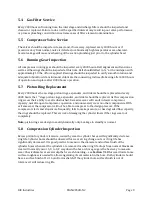
After performing the pre-startup system inspection, start the unit. When starting the compressor
for the first time or after servicing, check for leaks in the plumbing – see
Section 7.2
for
recommended leak check procedure. After correcting any leaks in the system, restart the unit and
observe gas pressures and temperatures. The pressure will increase based on back pressure from
the User’s downstream plumbing. Gas temperature will also rise in conjunction with the
compression ratio of each stage.
All shutdown devices and control logic should be tested before the system is put into autonomous
operation.
3.3
Normal Operating Conditions
The table below shows theoretical operating conditions—actual pressures and temperatures may
vary. Due to the inclusion of a back-pressure regulator in the compressor package, the discharge
pressure should always be a minimum of 1500 psig. Do not adjust the back-pressure regulator
setpoint as it keeps the 2
nd
stage floating piston from hitting the 2
nd
stage valve during normal
operation.
Stage
Pressure
(psig)
Temperature
(°F)
Suction
30 - 70
70
Interstage
300-600
300
Discharge
1500-2200
225
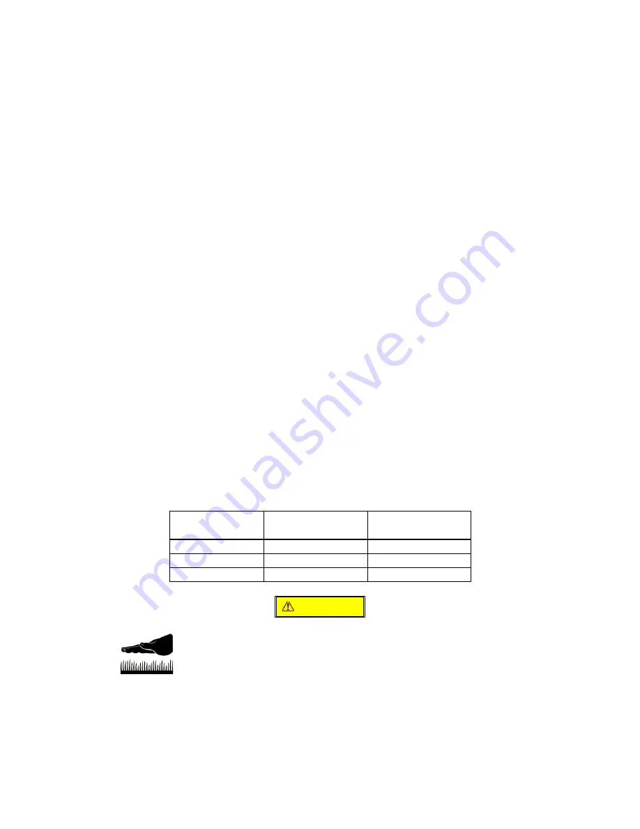
CAUTION
Cylinder heads and discharge lines are hot. Touching any part of
the cylinder heads or discharge lines can cause burns.
It is recommended that the
Service Log
in the appendix of this manual be used to note operating
pressures, temperatures, and maintenance done at hours of compressor operation. If pressures do
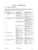
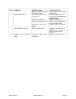
not fall near the above stated values, or vary from your historical pressures, see
Chapter 6 –
Troubleshooting
for corrective action.
Summary of Contents for 2PS-H-N2
Page 36: ...RIX Industries MAN 2PS2B N2 Page 28 FIGURE 1 COMPRESSOR CROSS SECTION FASTENER DETAIL...
Page 37: ...RIX Industries MAN 2PS2B N2 Page 29 FIGURE 2 COMPRESSOR CROSS SECTION PUMP DETAIL...
Page 38: ...RIX Industries MAN 2PS2B N2 Page 30 FIGURE 3 1ST STAGE VALVE DETAIL...
Page 39: ...RIX Industries MAN 2PS2B N2 Page 31 FIGURE 4 2ND STAGE VALVE DETAIL...
Page 40: ...RIX Industries MAN 2PS2B N2 Page 32 FIGURE 5 EXTERIOR FASTENER DETAIL...
Page 41: ...RIX Industries MAN 2PS2B N2 Page 33 FIGURE 6 MOTOR AND CONTROL BOX MOUNTING...
Page 42: ...RIX Industries MAN 2PS2B N2 Page 34 FIGURE 7 SUCTION PLUMBING DETAIL...
Page 43: ...RIX Industries MAN 2PS2B N2 Page 35 FIGURE 8 INTERSTAGE PLUMBING DETAIL...
Page 44: ...RIX Industries MAN 2PS2B N2 Page 36 FIGURE 9 FINAL DISCHARGE PLUMBING DETAIL...
Page 45: ...RIX Industries MAN 2PS2B N2 Page 37 FIGURE 10 COOLING FAN SUB ASSEMBLY DETAIL...
Page 46: ...RIX Industries MAN 2PS2B N2 Page 38 FIGURE 11 BELT INSTALLATION DETAIL...
Page 47: ...RIX Industries MAN 2PS2B N2 Page 39 FIGURE 12 GUARD MOUNTING DETAIL...
Page 48: ...RIX Industries MAN 2PS2B N2 Page 40 FIGURE 13 CONTROL BOX DETAIL 1 OF 2...
Page 49: ...RIX Industries MAN 2PS2B N2 Page 41 FIGURE 14 CONTROL BOX DETAIL 2 OF 2...
Page 50: ...RIX Industries MAN 2PS2B N2 Page 42 FIGURE 15 CONTROL BOX WIRING DIAGRAM...
Page 51: ...RIX Industries MAN 2PS2B N2 Page 43 FIGURE 16 ELECTRICAL SCHEMATIC...
Page 52: ...RIX Industries MAN 2PS2B N2 Page 44 FIGURE 17 FLOW SCHEMATIC...
Page 56: ......
Page 57: ......
Page 58: ......
Page 59: ......


