


HeatStation™ CONDENSING WATER BOILER
43
34-1161 05/17
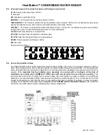
12.3 Internal Component Terminal Functions and Primary Pump Control
V1-V2:
Power to the Gas Valve, 120Vac.
F:
Not used.
PB:
Electronic Low Water Probe.
IGNITOR 1
– 2
: Power to the Hot Surface Ignitor, 120Vac.
CIRCULATOR 1
– 2
: Power to initiate Primary Pump Motor relay or starter. 120Vac. Do not attempt to power pump
directly through this source. Also used for motorized isolation valve relay. 120Vac.
OPTION 1
– 2
: Power to initiate DHW (Direct Hot Water) Pump. 120Vac. Do not attempt to power pump directly
through this source. Contract Riverside Hydronics for more information.
H1-H2:
Water Flow Switch is connected here.
P21-P22
: Low Gas Pressure Switch is connected here.
P31-P33
: High Gas Pressure Switch is connected here.
M1-M3
: Power supply to the Blower, 120Vac.
M2
: Not used.
G
: Ground to the Blower.
12.4 Connecting Isolation Valves
The CIRCULATOR output on the component terminal strip provides a 120 Vac, 0.5 amp pilot voltage to control a
boiler water isolation valve. Do not directly energize the valve actuator through these terminals. The wiring diagram
below illustrates the correct method for applying a an intervining relay with a separate power supply to drive the valve
actuator.
It is important that the isolation valve assembly be ordered with or configure at the time of
installation as a spring return NORMALLY OPEN valve
with an end switch to prove the open position
. This
will insure that in the event of a boiler fault or power outage, the valve returns to an open condition. As an additional
precaution, it is recommended that the valve open proving switch be wired through the C1 & C2 terminal on the Field
Access terminal strip to verify that the valve is open before the boiler is allowed to operate. In order to properly
configure the CIRCULATOR output refrence
Section 10.17
PIM DIP Switch Selectable Options.
DIP Switch #3
should be in the OFF position when configuring the control method below.