


HeatStation™ CONDENSING WATER BOILER
42
34-1161 05/17
The PIM determines its operating parameters by reading the identification code of an external plug-in ID card. The ID
card is connected to the PIM at the J6 connector.
NOTE
: This ID card must be present for the PIM and appliance to operate. This card selects the proper settings in
the PIM's memory for various appliance models. The first time a PIM is powered up attached to an ID card, the ID
card setting is stored in non-volatile memory. Once set, the PIM only operates with the correct ID card installed that
matches its internal ID settings. The PIM verifies the ID card at power-up and on each heating cycle.
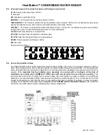
12 REMOTE CONNECTIONS
– TERMINAL STRIP
12.1
Making BMS/BAS remote connections for analog and binary (on/off) signals
A terminal strip for the remote connections is located in the junction box under the control panel and is accessed by
removing the two screws that secure the junction box cover.
IMPORTANT:
Do not use single strand bell wire for remote field connections to terminals R1-R2 and C1-C2. Use only
multi-strand copper wire. See table below for wire length and gauge:
WARNING: Turn off all electrical service to the appliance when accessing the remote connections and close
and fasten the control cabinet cover before restoring electrical service to the appliance. The remote
connection terminals are High Voltage or may become High Voltage. If the electrical service is not turned off
and these terminals are touched, a dangerous shock could occur, causing personal injury or death.
Coupez l'alimentation avant intervention sur l'appareil.
12.2 Field Access Terminal Functions - The following describes the functions of each of these terminals and the
proper method for interfacing with an Energy Management System:
L1-L2:
Used for incoming 120VAC power supply connection.
Terminal
L1
is the hot terminal (Black) and
L2
is neutral (White). See the product catalog or specification document
for circuit ampacity rating.
R1-R2:
Used to activate / de-activate boiler from remote master control. Terminals are wired to a relay in a remote
Energy Management System. When the relay closes, the circuit from R1 to R2 is completed and appliance controls
are enabled. This appliance ships from factory with a jumper between terminals Remove jumper when connecting to
a remote controller.
A1-A2:
Used to activate a remote alarm, signaling shutdown of combustion control. This is a dry contact.
This is a dry contact which provides a maximum 2 amp relay contact closure when the control system terminates
operation due to a tripped safety interlock (i.e.: air proving switch, high limit switch or flame sensor, etc.).
P1-P2:
Provides a 5 amp max contact closure to control remote equipment (i.e. mechanical room air louvers, draft
inducer or power vent, etc.). Do not directly energize pumps or motors through these terminals. If operation or
repositioning of the remote equipment is required for safe operation of the appliance, the remote equipment must
send a return proving signal to terminals C1-C2, via its proving switch, to confirming proper operation or repositioning
to enable the appliance to energize. This is a dry contact.
C1-C2:
Is used for proving operation of remote devices. The water flow switch is internally wired in series with this
circuit. Terminals can be wired to a proving switch on a remote device such as a power venter, louvers or a
combination of these in series. When all remote proving switches close including the internally wired water flow switch
the appliance controls are enabled. This appliance ships form the factory with jumper between terminals C1 and C2
that must be removed when a proving switch is connected.
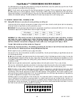
Wire Gauge
18 GA
16GA
14 GA
12 GA
Maximum Length
30 FT
50 FT
75 FT
100 FT