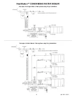


HeatStation™ CONDENSING WATER BOILER
25
34-1161 05/17
5.
Seal the vent pipe at the point where it passes through a wall or roof following the venting system manufacturer’s
installation instructions.
6.
For proper vent operation, attach the
vent system’s termination following the listed venting system manufacturer’s
installation instructions.
7.
Test the completed venting system for leaks following the venting system manufacturer’s installation instructions.
8.
Do not use a barometric damper with the HeatStation venting system. Barometric dampers are designed for use
with certain Category I negative pressure vent systems. The HeatStation Category IV vent system operates with
positive vent pressure and will not operate safely with a barometric damper.
9
OPERATING AND SAFETY CONTROLS
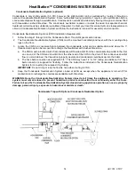
9.1 Pressure Relief Valve(s)
A Pressure Relief Valve(s) sized in accordance with the ASME Boiler and Pressure Vessel Code, Section IV is installed
in the boiler.
WARNING: Secure the relief valve discharge pipe to a suitable floor drain such that very hot water does not
openly splash during a significant relief valve discharge. If the relief valve discharge pipe is not routed and
secured to a suitable drain, hot water discharge can result in property damage, scalding and personal injury
or death.
WARNING: Do not plug the relief valve(s), use discharge piping smaller than the relief valve opening or install
a reducing coupling, valve or other restriction in the relief valve discharge line. Failure to comply with these
relief valves and discharge piping requirements can prevent the relief valve from providing its intended
pressure protection, which can result in a sudden loss of pressure containment that can cause property
damage, exposure to hazardous materials, personal injury or death.
Follow the relief valve manufacturer’s installation and operating instructions and all local regional and national
codes applicable to relief valve installation and discharge piping.
The relief valve discharge pipe must not be smaller than the relief valve opening and must be secured to prevent
it from lifting out of the drain under discharge pressure and must be routed to allow complete drainage of the valve
and piping.
Do not plug the relief valve(s) or install a reducing coupling, valve or other restriction in the relief valve discharge
line(s), as this will eliminate the critical water pressure protection it provides.
Thermal Expansion - A relief valve that periodically discharges may result from thermal expansion. To control these
periodic discharges, the boiler system must be provided with means to control expansion. Contact a boiler
professional to resolve this situation.
9.2 Flow Switch
The boiler requires a minimum flow of 30 GPM to operate. When flow is sufficient, the Flow Switch will close allowing
the operating control to energize. When flow is not sufficient, the Flow Switch will open, de-energizing the operating
control and interrupting a firing cycle or call for heat. The Flow Switch is located in the return (lower) header connection
pipe. The flow switch functions within the remote interlock safety circuit (see the Controls Section).
9.3 Blocked Flue Switch
A blockage in the venting or in the condensate trap will restrict the blower and increase pressure in the flue. A blockage
in the condensate trap will block the flue by causing condensate to fill the the flue collector and restrict the discharge
of flue gases. The Blocked Flue pressure switch (located in the control enclosure with tubing connected to the top of
the flue plenum) senses this pressure. The PIM monitors the Blocked Flue Switch. If the pressure becomes too high
(indicating a blocked condition), the PIM will not begin a call for heat.
9.4 Electronic Low Water Cut-Off
When the water level is above the electrode position in the boiler, the reset pushbutton will energize the control (LED
will be lit). The control remains energized until the water level drops below the electrode position (LED will not be lit).
Unless otherwise specified, there is a three-second time delay on decreasing level. Water level must be below the
probe location for full three seconds before control de-energizes. The Electronic Low Water Cut-Off is located in the
supply header.
IMPORTANT:
Probe Sensitivity = 26K ohms (most water/glycol mixtures up to 50% concentration may be used).