background image

Check for parts online at 

www.HuntRiversEdge.com

 or call 800-345-6007 M-F 8-5

2

Operator's Manual

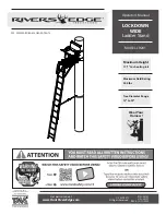
LOCKDOWN WIDE Ladder Stand

INTRODUCTION

Rivers Edge® Treestands are engineered with you the hunter in mind. We appreciate your purchase of one of our world class 

treestands. Follow these few simple instructions and your stand will provide you many years of trouble-free pleasure. Instructions 

should be kept in a safe place and reviewed at least annually. 
If for any reason you have a problem with your product or are missing any parts, 

DO NOT return to the retailer

, contact Rivers 

Edge® Customer Service Department at 800-345-6007 for assistance.

CONTENTS

Introduction/Warranty ..................................................................................................................................................................................................................2
Warnings .........................................................................................................................................................................................................................................3-4
Inspection and Maintenance ......................................................................................................................................................................................................4
Hardware Identification Chart ................................................................................................................................................................................................5-7
Assembly Instructions ............................................................................................................................................................................................................ 8-16
Warnings .......................................................................................................................................................................................................................................... 17
Setup and Use Instructions .................................................................................................................................................................................................18-23
The Ultimate Shooting Rail Use Instructions ...................................................................................................................................................................... 24
Finished Ladder ............................................................................................................................................................................................................................. 25
Illustrated Parts Breakdown................................................................................................................................................................................................26-27

WARRANTY

RETI offers a 

one-year warranty

 for all components of the treestand.  These warranties apply to the original owner with a proof of purchase.  These warranties 

begin on the date of purchase by the first retail consumer and continue for the period specified above.  These warranties apply to products that are not modified, 

abused or used in a manner that deviates from the product’s intended usage.  Minor fading in color is normal and is not covered by warranty.  Any corrosion 

of painted surfaces that occurs as a result of paint being removed or damaged is also not covered by warranty. RETI offers no other warranty expressed or 

implied.  Products for which warranty work has been approved must be sent directly to RETI and performed by RETI. 

To obtain warranty service and/or 

replacement instructions, you must obtain prior approval from RETI before shipping your package to us by calling our customer service department 

at 800-345-6007 or by writing to: Ardisam, Inc., P.O. Box 755, 1160 Eighth Avenue, Cumberland, WI 54829 for a return material authorization number 

(RMA#).

 All items must be shipped prepaid. RETI will, at no charge, repair or replace, in RETI’s sole discretion, any product that satisfies the conditions stated 

above. RETI retains the right to change models, specifications and price without notice.

This equipment has been manufactured under strict quality and safety guidelines. As with any equipment of this type, full understanding of the instructions and 

its use is mandatory and imperative for the safety of its user. RETI is not responsible for any damages or injuries sustained due to improper use or modification 

of any of its products, or resulting from any use which deviates from the product’s intended usage. RETI is not responsible for any injuries sustained due to 

failure to read and adhere to the instructions for use. Any misunderstanding or questions regarding the products of their use should be directed to RETI prior to 

any use. 

All RETI treestands are sold with a full body harness (“Fall Arrest System”) that meets standards recognized by the Treestand Manufacturer’s 

Association (“TMA”).

 It is the owner's sole responsibility to inspect the product regularly for damage, improper installation, or conditions that could jeopardize 

the ultimate safety of the product. Failure to use or improper use of the provided Fall Arrest System may result in serious injury or death. 

ALWAYS wear the 

provided Fall Arrest System while using this product.  Owner is responsible to understand and follow product field weight rating and must never 

exceed maximum weight rating.

 RETI is not responsible for any malfunction or injury resulting from normal wear and tear, damage caused by improper use, 

improper maintenance, negligence or accidents. This product, if used safely as intended, will provide trouble free service for the useful life of the product. We 

hope you will enjoy the quality of our products for years to come, and have a safe hunt.

Summary of Contents for LD201

Page 1: ...STANDARDS RECOGNIZED BY P N 35732 C N 35727 REV4 12 21 2020 2020 RETI All Rights Reserved Operator s Manual MODEL LD201 LOCKDOWN WIDE Ladder Stand Maximum Height 17 1 to shooting rail Wear Your Harnes...

Page 2: ...ousbycallingourcustomerservicedepartment at800 345 6007orbywritingto Ardisam Inc P O Box755 1160EighthAvenue Cumberland WI54829forareturnmaterialauthorizationnumber RMA All items must be shipped prepa...

Page 3: ...ever jump or bounce on a treestand to seat it to the tree Pull up a bow backpack or firearm or other equipment only after being secure in the treestand and a firearm must be pulled up with it unloaded...

Page 4: ...of structural damage or wear Never modify your stand in any way by making repairs replacing parts or altering by adding or attaching anything to it except if explicitly authorized in writing by the m...

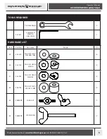
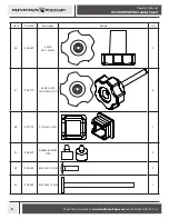
Page 5: ...Ladder Stand 7 16 WRENCHES 2 27477 4 MM ALLEN WRENCH INCLUDED 1 TOOLS REQUIRED HARDWARE LIST Item Part No Description Image Qty 29 23572 YELLOW PLASTIC WASHER 2 MM 8 30 35130 YELLOW CURVED SPACER 4 31...

Page 6: ...007 M F 8 5 6 Operator s Manual LOCKDOWN WIDE Ladder Stand Item Part No Description Image Qty 36 28839 KNOB M6 X 29 MM 2 37 36719 KNOB SILENT LADDER W STUD 6 38 29712 SQ PLUG 22 MM 1 41 48679 RUBBER B...

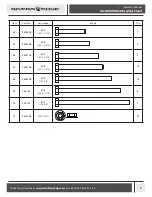
Page 7: ...CKDOWN WIDE Ladder Stand Item Part No Description Image Qty 44 48240B BOLT 1 4 X 1 1 2 IN 7 45 48250B BOLT 1 4 X 1 3 4 IN 4 46 48271B BOLT 1 4 X 2 1 4 IN 2 47 48270B BOLT 1 4 X 2 1 2 IN 14 48 48280B B...

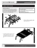
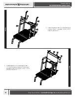
Page 8: ...olt combinations must be completely tightened All assembly must be done in this order at ground level before uprighting Do not remove labels warnings from product they are there for your safety Recomm...

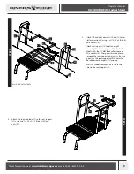
Page 9: ...seat support 12 to left and right armrests 10 and 11 using four 1 4 20 x 3 1 2 IN bolts 49 four 12 MM thick yellow spacers 32 and nuts 51 The spacers must be placed between the seat support and armre...

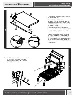
Page 10: ...STEP 5 STEP 6 51 9 10 11 47 25 44 9 51 7 5 Attach the backrest tubes 9 to the left and right armrests 10 and 11 using four 1 4 20 x 2 1 2 IN bolts 47 and nuts 51 6 Slide the backrest 25 onto the backr...

Page 11: ...t 43 bottoms out on the inside of the capped seat tube Secure the seat tensioner 14 to the seat 13 using one 1 4 20 x 1 1 2 IN bolt 44 and nut 51 Insert the 22 MM plug 38 into the end of the right sea...

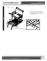
Page 12: ...e of adjustable shooting rail parts 26 into the shooting rail 16 Align the holes and secure together using two 1 4 20 x 1 1 2 IN bolts 44 and nuts 51 10 Attach the shooting rail assembly to the rest o...

Page 13: ...07 M F 8 5 13 Operator s Manual LOCKDOWN WIDE Ladder Stand STEP 11 mesh hidden for clarity 4 8 51 29 31 31 47 11 Attach the footrest 8 to the front platform section 4 using two 1 4 20 x 2 1 2 IN bolts...

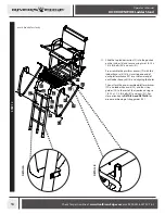
Page 14: ...ng two 1 4 20 x 1 3 4 IN bolts 45 and nuts 51 Pre assemble the platform braces 19 with the ladder hand rails 18 by inserting one end of each platform brace 19 into the lower end of each ladder hand ra...

Page 15: ...on 3 ladder section with stabilizer bar mount 21 middle ladders section 1 and the top ladder section 2 with the treestand top assembly The ladder sections are secured together with the six Silent Ladd...

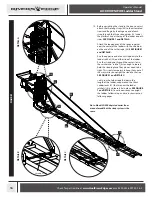
Page 16: ...pposite end of each strap down to the ladder ratchet 28 on either side of the ladder Run the strap down through the center slot in the ratchet and ratchet just enough to loosely hold the strap in plac...

Page 17: ...tree and stabilizer bar securely attached Failure to correctly perform these steps can cause the ladder to collapse buckle over backwards during the initial ascent to attach ratchet strap resulting in...

Page 18: ...f the tree 3 Position one person at bottom end of ladder This person has to prevent the ladder end from tilting up and from skidding across the ground when platform end is lifted 4 Position two people...

Page 19: ...side of the tree SEE FIGURE 3 10 Hook the large carabiner 57 to one of the long straps 55 that are hanging down near the tree SEE FIGURE 3 If the tree has branches between the ground and the top of th...

Page 20: ...r bar 22 to lift up and drop the strap that has the carabiner hooked to it over the branches a Hook the carabiner onto the end of the stabilizer bar as shown in FIGURE 4 b Then lift up and drop over e...

Page 21: ...iner nears the top you may have to use a back and forth sawing motion with the two straps so that the carabiner rises all the way up directly behind the bottom tree blade 15 The straps should be paral...

Page 22: ...d line up 16 Release the first clamp and extend only the bark biter section of the stabilizer bar until it contacts the tree Adjust the length of the stabilizer bar as needed and make sure it is paral...

Page 23: ...t of ratcheting mechanism and back around through tightening lever SEE FIGURES 12 A B 13 21 Wrap the ratchet assembly around the tree and hook other S hook through opposite hole on top tree blade Pull...

Page 24: ...red height and tighten them back up SEE FIGURE 14 2 To adjust the shooting rail in or out simply release the two clamp levers and slide the shooting rail to the desired position Then lock in place by...

Page 25: ...OCKDOWN WIDE Ladder Stand FINISHED LADDER RATCHET STRAPS LONG STRAP CONNECTED WITH CARABINER STABILIZER BAR CAM STRAP TELESCOPING STABILIZER BAR MIDDLE LADDER SECTION TOP LADDER SECTION ASSEMBLED PLAT...

Page 26: ...Stand ILLUSTRATED PARTS BREAKDOWN mesh hidden for clarity 51 35 37 23 47 2 1 1 21 3 28 51 46 24 34 33 22 18 47 19 51 45 51 51 23 47 6 23 45 44 15 51 29 4 48 39 31 47 31 8 40 20 48 51 5 51 16 44 27 26...

Page 27: ...AR TELESCOPING 1 23 35129 STRAP GUIDE 6 24 35131 INSERT STABILIZER BAR MOUNT 1 25 35151 BACKREST 1 26 35229 ADJUST SHOOTING RAIL 2 27 35374 INSERT SHOOTING RAIL 2 28 35715 RATCHET LADDER 2 29 23572 YE...

Page 28: ...improvements product images may not be exact Warning labels in some product images may have been removed for photography purposes only Props shown in photos not included Some assembly may be required...

Reviews: