7
Modes
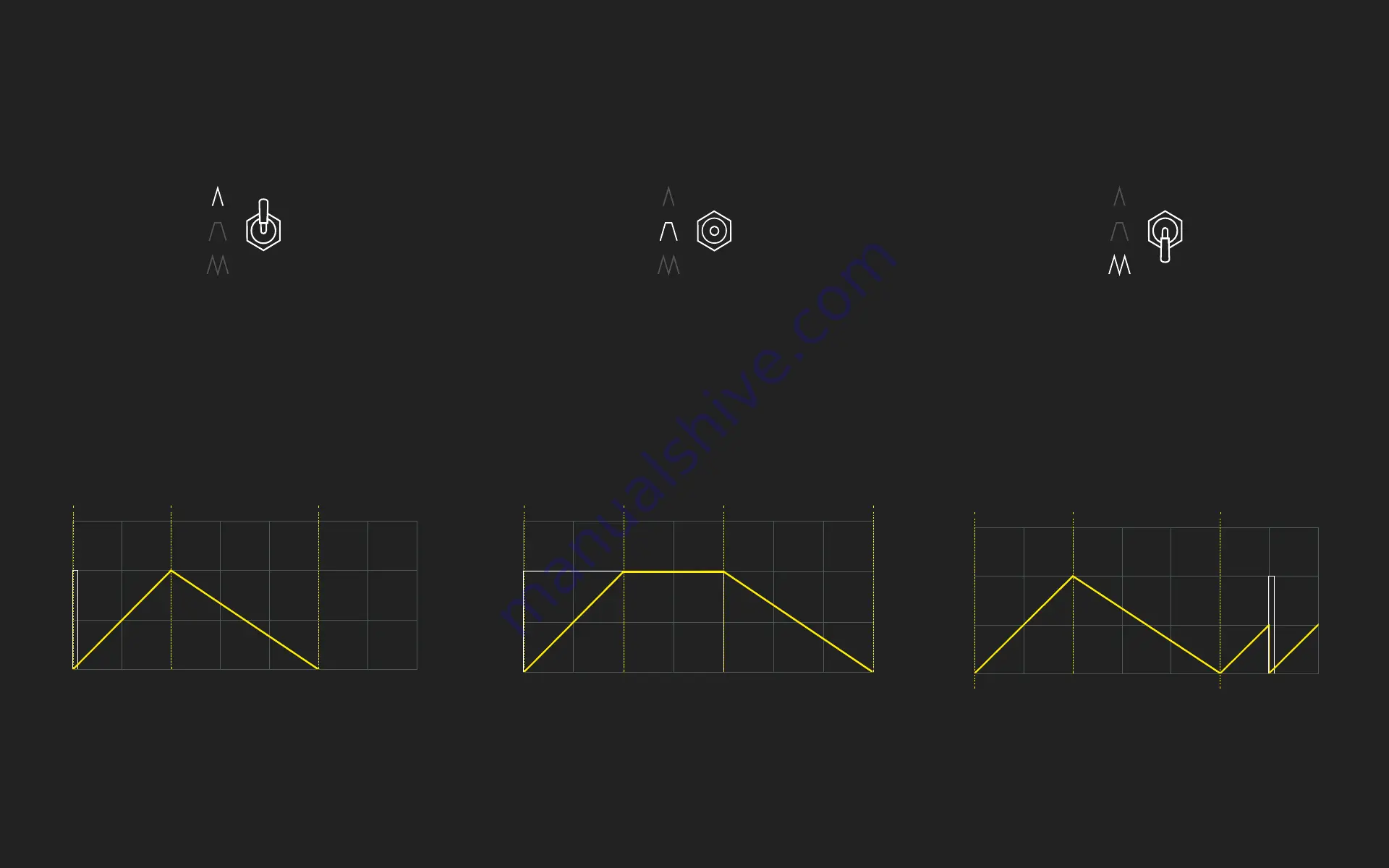
AD Mode
The module takes any signal as an input, turns it
into a trigger to launch a rising segment (attack)
and a falling segment (decay). The length of
these segments are defined by Attack and Decay
knobs. They are independent of the input signal.
ASR Mode
The module takes any signal as an input and
turns it into a gate. The attack phase is initiated
at the rising edge of the gate, the voltage is then
sustained during the length of the gate before
starting the release phase (controlled by Decay
knob).
Cycle Mode
Cycle loops the rising and falling segments ac-
cording to their lengths. Long lengths will result
in slow, low frequency oscillations (max 80s).
Short lengths rising and falling lengths will go to
audio speed (up to 2kHz). An incoming signal
can reset the LFO or sync the oscillator.
Attack phase
Trigger in
(V)
(t)
Decay phase
Attack phase
Gate in
Sustain phaseR
elease phase
(V)
(t)
Attack phase
Trigger in
(V)
(t)
Decay phase
Cycle


