CMC-TC Wireless I/O-Unit
16
Key
1
List of all sensors connected to the Processing
Unit.
Clicking the sensor name displays the configura-
tion page of the sensor
2
Link to the sensor configuration
(see 8.1.5)
3
Link to the status window (see 8.1.3)
4
Clear – acknowledge events
8.1.5 Sensor Configuration
You can individually set the attached sensors.
Because the structure of the configuration over-
view is generally always identical, it is shown here
as an example.
To reach this page, click the
tool icon or click
the sensor name directly.
1
2
3
4
5
6
7
8
9
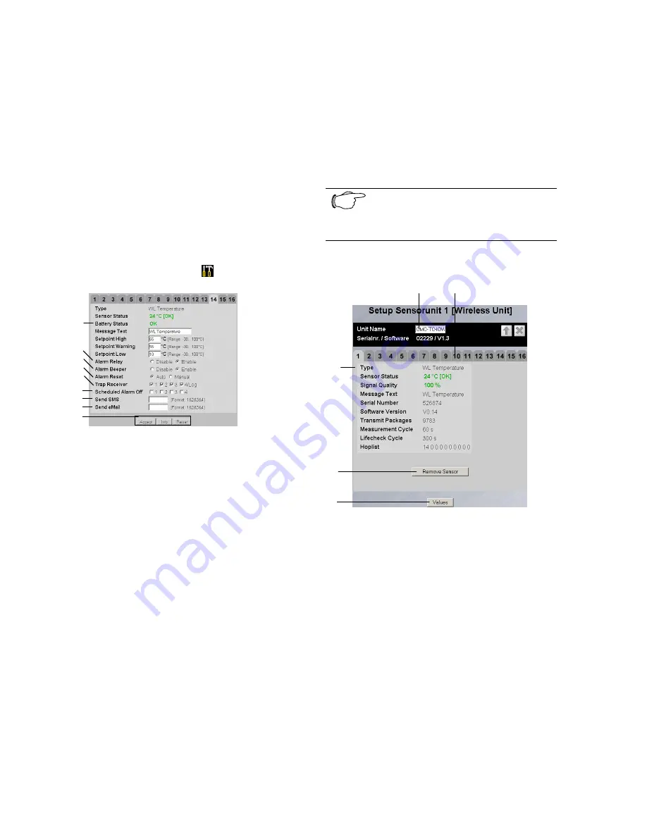
Fig. 25 Configuring the sensor – overview
Key
1
Battery status
OK – battery OK
low – change battery
2
You can set for each sensor whether (enable) or
not (disable) the alarm relay is to be switched for
an alarm.
3
You can set for each sensor whether (enable) or
not (disable) the integrated alarm beeper is to be
activated for an alarm.
4
You can set for each sensor type whether after a
warning or alarm status the CMC-TC PU should
self-acknowledge (auto) or the administrator must
acknowledge manually (manual).
5
By clicking the individual option fields you can
determine to which of the entered trap-receivers
the traps for this sensor are to be sent.
6
By clicking the individual option fields you can set
which alarm configuration is to be enabled or dis-
abled. You can specify the individual functions in
the "Setup – Timer" menu item and assign the
associated scheduler.
7
Enter here the numbers 1 to 4 of the mobile wire-
less numbers that should receive an SMS when
an alarm is issued. To create the mobile wireless
numbers, please consult the operating manual of
the CMC-TC Processing Unit. The numbers must
be entered separated by an "&" character (e.g.
1&2&3&4).
8
Enter here the numbers 1 to 4 of the email adress
that should receive an email when an alarm is is-
sued. To create the email adress, please consult
the operating manual of the CMC-TC Processing
Unit. The numbers must be entered separated by
an "&" character (e.g. 1&2&3&4).
9
Accepting the changes.
Info page for the specific wireless sensor.
(changes will not be accepted by clicking Info)
Reset all settings to the default values.
Note!
Further setting possibilities are de-
scribed in the Wireless Sensor operat-
ing manual.
8.1.6 Sensor Information
1
2
3
4
5
Fig. 26 Sensor information
Key
1
Name of the I/O-Unit to which the sensor is regis-
tered.
2
Tabs for additional sensors of the Processing
Unit.
3
Detailed information for the selected sensor
(here: Sensor 1)
Type
: Sensor type
Sensor Status
: Current measured value or status
of the sensor
Signal Quality
: Signal quality of the Sensor –
I/O-Unit connection
Message Text
: Message text for alarm messages
Serial Number
: Serial number of the sensor
Software Version
: Version number of the sensor
software
Transmit Packages
: Data packages transmitted
from the sensor to the I/O-Unit
Measurement Cycle
: Interval between two
measurements
Lifecheck Cycle
: Interval between the
transmission of two Lifecheck packets. An Error
will be reported after 4 consecutive lifecheck sig-
nal losses.


