


Commissioning 7
CMC-TC Wireless I/O-Unit
11
EN
1
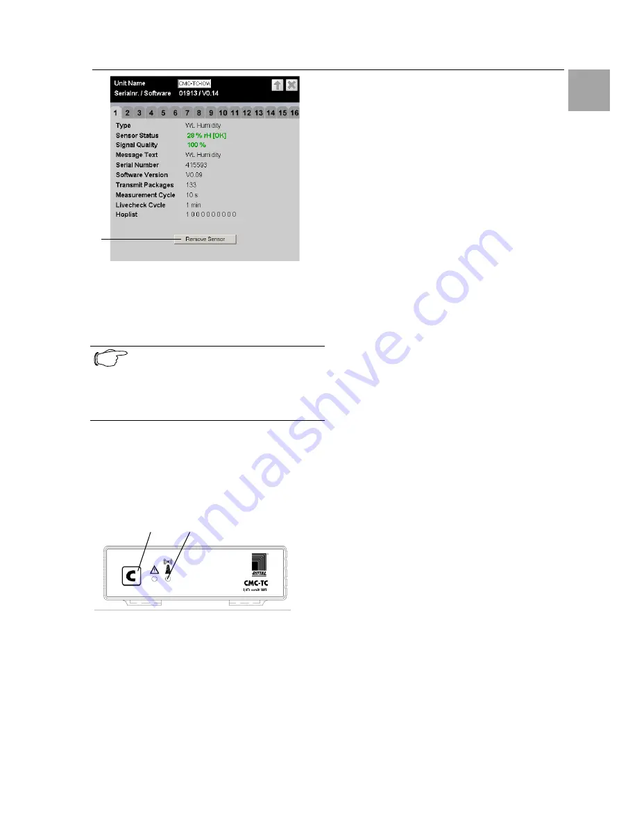
Fig. 18
Sensor Information
Key
1
Remove Sensor
button
Click the
Remove Sensor
button to remove the sen-
sor from the I/O-Unit.
Note
The communications timing between the
I/O-Unit and the sensor can require that
Remove Sensor
must be clicked several
times before the remove command is ac-
cepted.
The sensor has now been removed and will no
longer be listed in the sensor overview. To recon-
nect the sensor, proceed as described in Section
7.2.
7.4 Closing Programming Mode
1
2
Fig. 19 Closing programming mode
Key
1
C key
2
Wireless connection LED
To close the programming mode, press the C key
on the CMC-TC Wireless I/O-Unit for two seconds.
The Wireless Connection LED will change to green.
If the programming mode is not closed manually, the
CMC-TC Wireless I/O-Unit returns automatically to
normal mode two minutes after the last registration
action.
7.5 Tips and Notes for the Sensor
Placement
To prevent malfunctions and to ensure reliable op-
eration, the sensors should be positioned as de-
scribed in Subsection 7.5.1. Detailed fundamental
information for the used wireless technology is de-
scribed in Subsection 7.5.2.
Before starting the measurement, all I/O-Units and
repeaters must be installalled and all antennas must
be aligned.
7.5.1 Tips for the Calibration of the Sen-
sor Locations
To ensure the best possible reception of the individ-
ual sensors, the suitability of each sensor location
must be tested in advance using the wireless meas-
uring system sensor (DK 7320.242).
Procedure:
i.
Place the I/O-Unit into operation at the
planned location as described in Section
7.1.
Tip: Before starting the calibration, succes-
sively connect all sensors to the I/O-Unit.
This causes the sensors to be placed in
front of the measuring system sensor in the
registration list of the Processing Unit II.
This simplifies the subsequent administra-
tion.
ii. Connect the wireless measuring system
sensor to the I/O-Unit (see Section 7.2). To
do this, proceed as follows:
Place the I/O-Unit in programming mode
(press the
C key
for three seconds) > press
the
key
on the wireless sensor for five sec-
onds (resets the sensor) > press the
key
on
the wireless sensor 1 second > the LED
flashes once briefly > sensor is registered >
leave programming mode of the I/O-Unit
(press the
C key
for two seconds, the wire-
less connection LED on the I/O-Unit lights
up green).
iii. Place the sensor attachment bracket at the
required sensor location (true for all sensor
types). The sensor front side edge must
point later in the I/O-Unit direction.
iv. Place the measuring system sensor on the
attachment bracket. The sensor position
during the measurement must be the same
as the operation position.
v. Perform a one-minute measurement with
the measuring system sensor: Press the
key
on the measuring system sensor >
the result of the previous measurement will
be displayed for five seconds > "1" flashes
in the display (indicates the one-minute
measurement) > if a different number is dis-
played flashing, press the
key
several times
until the "1" appears > the measurement


