13
PDR/PDM Montageanleitung/PDR/PDM assembly instructions/PDR/PDM – Notice de montage
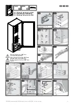
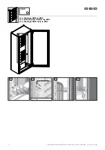
10.1. Montage PDR
10.1. Installing the PDR
10.1. Montage PDR
D
Das Rittal PDR-System ist im Data Center auf-
zustellen, in dem es zuverlässig vor äußeren
Einfl üssen geschützt ist.
Zu berücksichtigen sind auch die Einhaltung
der zulässigen Umgebungstemperatur- und
Feuchte-Einsatzbereiche sowie die anwen-
dungsbezogene geforderte IP-Schutzart. Die
entsprechenden Angaben sind im Abschnitt
3.3 Technische Daten hinterlegt.
䡲
Bei der Verwendung von Zubehör in Verbin-
dung mit dem Rittal PDR ist die Montage-
und Bedienungsanleitung des Zubehörs und
des Rittal PDR zu beachten.
䡲
Der Schutzleiter ist auf jeden Fall über die
Anschlussleitung der Einspeisung anzu-
schließen.
䡲
Der Anschluss des N-Leiters muss über die
Anschlussleitung erfolgen.
䡲
Empfohlen wird für den PE und N der
gleiche Querschnitt wie bei den Anschlüssen
der Phasen.
䡲
Hinweis:
In Data Center wurden Ströme auf dem
N-Leiter beobachtet, die den Strömen der
Phasen gleich kommen.
Montage PDR
Der Schrank kann mit und ohne Sockel
montiert werden. Die Kabeleinführung für die
Einspeisung ist von unten durch eine Lücke im
Bodenblech vorgesehen.
Der Boden für die Montage muss gerade und
eben sein. Er muss ausreichend fest sein, um
eine sichere Befestigung des Schrankes an
den Boden zu gewährleisten, z.B. mit Dübeln.
Der Schrank muss auf jeden Fall fest mit dem
Boden verbunden werden, um ein Umstürzen
des Schrankes zu verhindern.
Seitliches oder rückseitiges Anreihen mit TS 8
Schränken ist möglich. Die Anreihmontage
und das notwendige Material entnehmen Sie
bitte der TS 8-Montageanleitung. Die Öff -
nungen des Rahmens zu benachbarten TS 8
Schränken müssen in allen Fällen mit einer
Schottwand verschlossen werden. Schott-
wände befi nden sich im TS 8-Zubehör.
Der Anschluss zur Hauptverteilung muss mit
ausreichendem Querschnitt verlegt werden.
Angaben über den zu installierenden Quer-
schnitt sind im Anhang A der EN 61439-1
enthalten.
Das Verbinden des PDR mit der Hauptvertei-
lung darf nur durch eine Elektrofachkraft (siehe
Abschnitt 2 ) durchgeführt werden.
Das Anschlusskabel muss durch die Zugent-
lastung gesichert werden. Die Kabeldurchfüh-
rung durch die Gehäusewand der Einspeisung
muss über die vorgesehenen Tüllen erfolgen.
Bei der Verwendung des PDR mit 3-poligem
Hauptschalter ist es in einem TN-C Netz
möglich, N und PE an der Einspeiseklemme
zu überbrücken. Hierzu ist eine PEN-Brücke
Typ WQV 70N/2 vom Klemmenhersteller
Weidmüller zu verwenden.
EN
The Rittal PDR system is to be installed in the
data centre where it is reliably protected from
external infl uences.
Attention must be paid to maintaining the
ambient temperature and humidity ranges, as
well as the IP protection category as required
for the specifi c application. The appropriate
information is given in Section 3.3 Technical
specifi cation.
䡲
When using accessories in connection with
the Rittal PDR, the installation and operating
instructions for the accessories and for the
Rittal PDR must be observed.
䡲
In every case the PE conductor must be
connected using the connection cable.
䡲
For connection of the N conductor the con-
necting cable must be used.
䡲
The same cross section as for the connec-
tions of the phases is recommended for the
PE and N conductors.
䡲
Note:
In data centres, currents have been
observed on the N conductor which are
equal to the currents of the phases.
Installation PDR
The enclosure can be installed with or without
base/plinth. The cable entry for the infeed is
provided for from below through a gap in the
gland plate.
The fl oor must be fl at and level for installa-
tion. It must be suffi ciently fi rm to ensure safe
fastening of the enclosure to the fl oor, e.g.
with fastening plugs. The enclosure must
be connected fi rmly with the fl oor under all
circumstances in order to prevent tilting.
Baying with TS 8 enclosures on the sides or at
the rear is possible. For information on baying
installation and necessary materials, see
TS 8 installation instructions. The opening of
the frame to neighbouring TS 8 enclosures
must in every case be closed with a partition.
Partitions are part of the TS 8 accessories.
For the connection to the main distribution
a suffi cient cross section must be provided.
Information concerning the cross section
to be installed is given in Appendix A of
EN 61439-1.
Connection of the PDR with the main distribu-
tion may be made only by a skilled electrician
(see Section 2).
The connection cable must be protected by
the strain relief. The cable entry through the
enclosure panel of the infeed must be made
using the pertinent grommets.
When using a PDR with 3-pole main switch it
is possible in a TN-C net to bridge N and PE
at the infeed terminal. For this, a PEN bridge
type WQV 70N/2 from terminal manufacturer
Weidmüller is to be used.
F
Le système PDR Rittal doit être installé dans la
salle informatique où il est protégé fi ablement
contre les infl uences extérieures.
Le respect des plages de température
ambiante et plages d'humidité fi ables ainsi que
le type de protection IP en fonction de l'appli-
cation doivent être pris en compte. Les indica-
tions correspondantes sont enregistrées dans
la section 3.3 Caractéristiques techniques.
䡲
Lors de l'utilisation des accessoires liées au
PDR Rittal, la notice de montage et d'utili-
sation des accessoires et du PDR Rittal doit
être respectée.
䡲
Dans tous les cas, le câble de protection
doit être raccordé par le câble de raccorde-
ment de l'alimentation.
䡲
Le raccordement du conducteur neutre doit
s'eff ectuer par le câble de raccordement.
䡲
Pour la terre et le neutre, la même section
que pour les raccordements des phases est
recommandée.
䡲
Remarque :
Dans les salles informatiques, des courants
s'apparentant aux courants des phases ont
été observés sur le conducteur neutre.
Montage PDR
L'armoire peut être montée avec et sans
socle. L'introduction des câbles pour l'ali-
mentation est prévue depuis le bas par un
emplacement dans la tôle de fond.
Le sol pour le montage doit être droit et plat. Il
doit être suffi samment résistant pour garantir
une fi xation sécurisée de l'armoire au sol, par
ex. avec des chevilles. Dans tous les cas,
l'armoire doit être solidement fi xée au sol pour
éviter tout basculement.
La juxtaposition latérale ou arrière avec les
armoires TS 8 est possible. Le montage
juxtaposé et le matériel nécessaire sont décrits
dans la notice de montage TS 8. L'espace
ouvert entre le PDR et une armoire TS 8
juxtaposée doit être obturé par une cloison
de séparation. Les cloisons de séparation se
trouvent dans les accessoires TS 8.
Le raccordement à l'alimentation principale
doit être acheminé avec une section suffi -
sante. Les indications concernant la section à
installer fi gurent dans l'Annexe A de la norme
EN 61439-1.
La connexion du PDR à l'alimentation prin-
cipale doit être réalisée uniquement par un
électricien (voir Section 2).
Le câble de raccordement doit être protégé
par la décharge de traction. Le passage de
câbles par la paroi du boîtier de l'alimentation
doit s'eff ectuer par les passe-câbles prévus.
Dans le cas d'utilisation d'un PDR avec un
commutateur 3 pôles, il est possible avec un
régime de neutre TNC de shunter la terre et le
neutre. Pour cela, il faut utiliser un connecteur
transversal de type PEN Weidmüller WQV
70N/2 réf. 106350.
EN
F
D


