+
INSU 5Dx
Operating Manual
Digital Insulation Tester
Page 1: ...INSU 5Dx Operating Manual Digital Insulation Tester...
Page 2: ...ings 8 Chapter 4 Connections of test leads to meter 9 Chapter 5 Measurement modes of the meter 11 5 1 IR Mode 11 5 2 DAR Mode 13 5 3 PI Mode 16 5 4 Step Mode 19 5 5 Ramp Mode 23 5 6 Dielectric Dischar...
Page 3: ...Charging 48 Chapter 12 Insulation Resistance Measurement for various Equipments 49 12 1 Transformers 49 12 2 Circuit breakers 50 12 3 Cables 50 12 4 Current transformers 51 12 5 Motors 51 Chapter 13 C...
Page 4: ...ectric Absorption Ratio DAR measurement is a diagnostic test similar to the Polarization Index PI but DAR takes the ratio of the Insulation Resistance usually measured at 30 sec and 1 min Dielectric D...
Page 5: ...itoring software for window system and an interactive mobile application for android File Explorer It has le explorer to view the datalog le on TFT display Audio Read Out Audible test result on comple...
Page 6: ...should be treated like additional safety devices and not a substitute for the general practices Insulation testing in wet conditions can be hazardous It is recommended that the instrument should not b...
Page 7: ...ing do not allow the liquid to come in contact with skin or eyes If by mistake you make contact wash the affected area with water and contact doctor Keep the battery away from children Do not expose t...
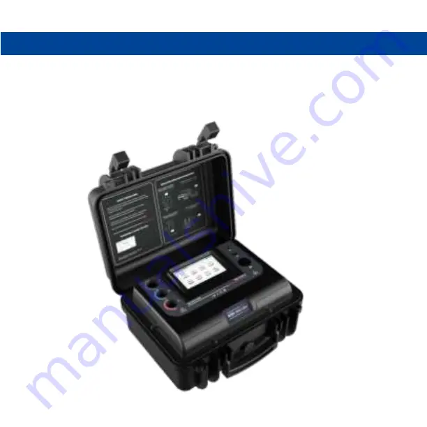
Page 8: ...CHAPTER 3 BASIC COMPONENTS AND INDICATIONS IN THE METER 7 5 6 4 1 2 3 8 7...
Page 9: ...tion 6 Speaker 7 Protective cover 8 TFT touch screen display 3 2 BASIC INDICATIONS AND THEIR MEANING Mains connected Battery charging Bluetooth mode Breakdown mode Burn mode Battery cannot supply nomi...
Page 10: ...the probe handle for the single probes Guard and positive and double probe which is connected to the negative terminal Both the handles have a rotor for locking the probe to the meter Due to the locki...
Page 11: ...10 Then push the probes into the meter and rotate the probe rotor as shown below so that the probe gets locked to the meter...
Page 12: ...e main measurement screen will appear To setup the basic settings of the mode press the icon The control window will appear as shown below Here you can set the voltage using the voltage up and down in...
Page 13: ...ter setting up all the basic settings press the button to go back to the main measurement screen All these control settings are stored by the meter so that the next time you start the meter you do not...
Page 14: ...ll you about the le number You can press the OK button on the message box in order to go back to the measurement screen 5 2 DAR Mode DAR Dielectric Absorption Ratio is de ned as the ratio of insulatio...
Page 15: ...DAR of greater than 1 4 indicates that the insulation is in an excellent condition The steps to take a test in DAR mode are as follows To enter the DAR mode press the icon on the home screen and follo...
Page 16: ...can be set in the control window with the help of their corresponding arrows The up arrow will increase the time and the down arrow will decrease the time After setting up all the basic settings pres...
Page 17: ...ng this button a message will appear to tell you about the le number You can press the OK button on the message box in order to go back to the measurement screen 5 3 PI Mode PI Polarization Index is d...
Page 18: ...eater than 4 indicates that the insulation is in an excellent condition The steps to take a test in PI mode are as follows To enter the PI mode press the icon on the home screen and the following scre...
Page 19: ...can be set in the control window with the help of their corresponding arrows The up arrow will increase the time and the down arrow will decrease the time After setting up all the basic settings press...
Page 20: ...tell you about the le number You can press the OK button on the message box in order to go back to the measurement screen 5 4 Step Mode In the step voltage test 5 test voltages are applied to the DUT...
Page 21: ...V 5 volts So in the last interval the test voltage will become V volts The value at the end of each interval is stored by the meter The steps to take a test in STEP mode are as follows To enter the st...
Page 22: ...e you start the meter you do not need to do these settings again Then connect the test leads to the equipment whose Insulation Resistance has to be measured On the measurement screen press and hold th...
Page 23: ...ply the meter will not be able to deliver 5000V to a load resistance of below 10 M SCREEN 1 SCREEN 2 SCREEN 3 VOLTAGE AT LEADS DUT VOLTAGE DURING TEST SET VOLTAGE VOLTAGE AT EACH STEP CURRENT AT EACH...
Page 24: ...ter than short circuit current limit which can be set in the settings window It will be discussed in detail in the further chapters The test time in this test is determined by the nal voltage and the...
Page 25: ...to do these settings again Then connect the test leads to the equipment whose Insulation Resistance has to be measured On the measurement screen press and hold the button for about 3 seconds and then...
Page 26: ...ter pressing this button a message will appear to tell you about the le number You can press the OK button on the message box in order to go back to the measurement screen SCREEN 2 SCREEN 3 VOLTAGE DU...
Page 27: ...for full absorption to take place in an insulation material The discharge timer t2 defaults to 1 minute Timer settings t1 and t2 are adjustable On completion of the test the instrument uses the curren...
Page 28: ...ntrol window will appear as shown below Here you can set the voltage using the voltage up and down in steps of 10V below 1000V and in steps of 25V above 1000V There is also a standard voltage button t...
Page 29: ...connect the test leads to the equipment whose Insulation Resistance has to be measured On the measurement screen press and hold the button for about 3 seconds and then release it to start the test Th...
Page 30: ...that if in any test the test current reaches beyond 1 mA the meter will take a response time of about 10 min to display accurate readings for a current below 10 nA This time can be reduced by turning...
Page 31: ...utton on the home screen of the meter The following screen will be displayed Additionally the meter also displays the voltage at the test leads DUT in other modes IR DAR PI STEP and RAMP before the st...
Page 32: ...ata point Test duration Duration between 2 data points Sample rate 5min 1 sec data point 5 min 01 sec 10 min 2 sec data point 10 min 01 sec 15 min 3 sec data point 15 min 01 sec 20 min 4 sec data poin...
Page 33: ...ion resistance vs time for a given DUT On the home screen go to your desired test mode IR DAR PI STEP or RAMP using their corresponding button After this run the test as per the instructions given in...
Page 34: ...w you can press the button Along with the data of the test the graph of the test is also stored when you save the le The saved graph can be viewed in the le explorer Also you can view the graph while...
Page 35: ...he le explorer and to read the data in your desired les you have to follow the following steps On the home screen enter any mode using their respective icon IR DAR PI STEP or RAMP Press the button to...
Page 36: ...ng the scrolling arrows You can also view the graph for the test by pressing the button In case the memory gets fully occupied you can delete individual les by going to the le and pressing the button...
Page 37: ...read out the Polarization Index PI and in the DAR mode it will read out the Dielectric Absorption Ratio DAR after the test is completed This feature can be turned on off by the user So to check wheth...
Page 38: ...ooth usb get reset to their default values once the meter is restarted The settings window is as shown below 9 1 SLEEP Mode Settings As the meter is a battery operated device power saving plays a very...
Page 39: ...you can change the sleep time by pressing on the minutes button and a keyboard will appear where you have to enter the minutes and press button The sleep mode can also be turned ON OFF by clicking on...
Page 40: ...stores customer information in the le in which the customer can write the test speci c data like customer ID and name This can also be set in the setting window by pressing the button after which the...
Page 41: ...have to enter the customer ID name and then press the key 9 4 Brightness Settings You can also change the brightness of the screen as per your requirement There are three settings available You can c...
Page 42: ...nge the breakdown burn setting by clicking on the icon in the bottom left corner which indicates the present breakdown burn setting Difference between breakdown mode and burn mode Breakdown mode In th...
Page 43: ...rd or breakdown This is displayed when the voltage doesn t reach the desired value and the current is below 1 mA This is generally displayed when the user accidentally shorts the positive and guard te...
Page 44: ...ng the desired value on the keyboard and then pressing the button You can also turn on off go no go by clicking on off button shown in the above window The icon of this button shows whether the go no...
Page 45: ...ads out the insulation resistance values and other parameters like Polarization index PI and Dielectric Absorption Ratio DAR with the help of powerful speaker This feature can be turned on off by pres...
Page 46: ...01nA to 6mA Accuracy 5 0 2 nA Test voltage Accuracy 7 0 10 V nominal test voltage 45 Measuring Range Frequency Intrinsic Error 3 10D 20V 600V AC DC 45 Hz 500 Hz 100 V Nominal voltage 250 V 500 V 1000...
Page 47: ...IP 52 Applicable Standards Reference Conditions o Ambient Temperature 23 C 2 k Relative Humidity 45 55 Measured quantity frequency 50 Hz 10 Hz Line voltage waveform Sine wave Battery Voltage 11 1V 1 O...
Page 48: ...voltage category 600 V CAT IV Test voltage 7 4 KV AC Pollution degree 2 Dimensions L X B X H 360mm x 310mm x 195mm Weight Approx 5 kg Accessories a Standard scope of supply 1 In built Li ion rechargea...
Page 49: ...Hz AC supply Then turn on the switch of the socket and the mains power LED will turn ON to indicate the presence of mains Also the power cord symbol will appear on the task bar as shown below Also the...
Page 50: ...Following are the connections schemes for insulation resistance measurement for different equipments 12 1 TRANSFORMERS HV winding with 3 phases short to LV winding with 3 phases short HV winding with...
Page 51: ...Bottom to earth with guard to body Positive terminal of insulation tester Negative terminal of insulation tester G Guard terminal of insulation tester G Positive terminal of insulation tester Negativ...
Page 52: ...RS 12 5 MOTORS Positive terminal of insulation tester Negative terminal of insulation tester Positive terminal of insulation tester Negative terminal of insulation tester G Guard terminal of insulatio...
Page 53: ...e USB by touching on the USB bluetooth When the icon will have icon of USB it means USB has been selected Then go back to home screen of the meter and then connect the USB cord received with the meter...
Page 54: ...of the installed device as shown below Then install the software provided with the device Then select the COM port in the software and press the connect button Then message will be displayed Press ok...
Page 55: ...Settings More Settings and turn on the bluetooth by touching on the USB bluetooth When the icon will have icon of bluetooth it means bluetooth has been selected Then go back to home screen of the mete...
Page 56: ...55 Then click on 5Dx_xxxxxxxxx where xxxxxxxxx is serial number and then press next button The computer will pair with the device and the following screen will appear Click on the close button...
Page 57: ...the driver is installed and then driver installed message will appear Now again right click on the bluetooth icon and click on show bluetooth device Then right click on 5Dx_xxxxxxxxx and click proper...
Page 58: ...hen install the software provided with the device Then select the COM port in the software and press the connect button Then press ok button as shown below and the device will be connected to the comp...
Page 59: ...d turn on the bluetooth by touching on the USB bluetooth When the icon will have icon of bluetooth it means bluetooth has been selected Then go back to home screen of the meter Install the mobile appl...
Page 60: ...59 Then press the button shown in the gure Then in the drop down menu press the connect button Then the following screen will be displayed and the meter is now connected to your phone...