Rinnai REU-VR2426WS Solar 26 Service Manual Download Page 19

REU-VR2626WB (B26) /REU-VR2426WS (S26) /REU-VRM2626WG (INF26)

- 16 -

Issue 3 - 13/11/14 ©Rinnai
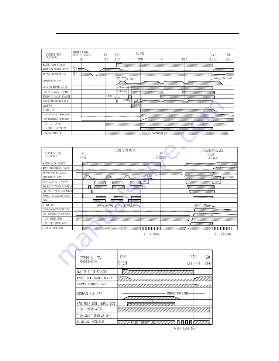
10.  Time Charts

Normal Combustion

Note: By pass control device fitted to model 2630 only. 

Mis-Ignition / Flame Failure 

Abnormal Pre-Purge (Air Supply/Exhaust Blockage) 

Summary of Contents for REU-VR2426WS Solar 26

Page 1: ...SERVICE MANUAL To Suit Models Does NOT Suit any other Models REU VR2626WB B26 REU VR2426WS S26 REU VRM2626WG INF26...

Page 2: ...Gas Association as compliant to relevant Australian Standards All Rinnai products are Certified to WaterMark by SAI Global WaterMark certification is awarded to products and fittings complying with s...

Page 3: ...hout notice Failure to comply with these instructions may result in serious personal injury or damage to the appliance This manual has been published by Rinnai Australia Engineering Technical Group We...

Page 4: ...agram 10 6 Smartstart 11 7 Operational Flow Chart 13 8 Operation Principles 14 9 Main Components 15 10 Time Charts 16 11 Wiring Diagram 17 12 Dip Switch Settings 18 13 Fault Finding 19 14 Component an...

Page 5: ...circuit kcal h kilocalorie per hour kPa kilopascals LED light emitting diode L min Litres per minute mA milliamps MJ h megajoule per hour mm millimetres mmH2O millimetres of water gauge pressure OHS...

Page 6: ...tection 90 W Delivery temperatures 40 C 42 C 50 C 55 C 60 C 65 C 75 C set by combination of dip switches on PCB NOTE 2426WS must be preset to 70 C Water flow control Water flow sensor electronic water...

Page 7: ...control device Maximum hot water capacity raised 25 C 26 L min Water pressure required to achieve maximum hot water capacity 180 kPa Maximum water flow 26 L min Water pressure required to achieve max...

Page 8: ...er electrical power supply is stopped if the temperature exceeds 129 C Water Pressure Relief Valve Safeguards the water circuit against excessive inlet pressure Opens at 2060 kPa closes at 1470 kPa El...

Page 9: ...hown below Water Flow vs Pressure Graphs 26 5 0 5 10 15 20 25 30 35 0 50 100 150 200 250 300 Inlet pressure kPa Outlet flow litres minute 2426 2626 P kPa 0 10 20 30 40 50 60 70 80 90 4 PLQ 5 3 8 10 3...

Page 10: ...Water inlet from wall 68 H Cold Water inlet from centre 10 I Gas Connection from wall 77 J Gas Connection from centre 83 Gas Length from base 40 Cold Length from base 50 Hot Length from base 42 Gas Fi...

Page 11: ...d working order and installed with the correct polarity within the wireless controller Battery polarity details on rear of wireless controller Ensure distance between wireless controller and transceiv...

Page 12: ...ore Question 2 Fig 5 Fig 6 Is the water heater marked to state it delivers water not exceeding 50 C IF YES No further action required IF NO You will need to program the kitchen controller to enable se...

Page 13: ...EU VRM2626WG INF26 10 Issue 3 13 11 14 Rinnai 5 Cutaway Diagram Note This cutaway diagram is of a general nature Some details may be different on some models Part No Name Material 0 1 2 3 4 2 4 4 1 4...

Page 14: ...ter and the hot water outlets before any outlets are opened using the flow and return pipework principle This results in water savings and reduced waiting time for heated water delivery from the outle...

Page 15: ...t r o l 7 0 0 k P a V a l v e M a n d a t o r y Cold Water Supply Smartstart installed with Rinnai gas boosted solar hot water system Refer to Rinnai manuals supplied with appliances for important ins...

Page 16: ...REU VR2626WB B26 REU VR2426WS S26 REU VRM2626WG INF26 13 Issue 3 13 11 14 Rinnai 7 Operational Flow Chart...

Page 17: ...will automatically control operation of the internal components to achieve the programmed delivery temperature When a high temperature rise is required the PCB may cause the Water Flow Sensor to clos...

Page 18: ...chieved through the use of servo driven water flow and bypass valves Note only some models have a by pass valve fitted Both servo motors are controlled by the PCB The Water Flow Valve restricts the fl...

Page 19: ...VR2426WS S26 REU VRM2626WG INF26 16 Issue 3 13 11 14 Rinnai 10 Time Charts Normal Combustion Note By pass control device fitted to model 2630 only Mis Ignition Flame Failure Abnormal Pre Purge Air Sup...

Page 20: ...ALVE POV P P Y FLAME ROD SV1 SV0 Bk SV2 Bk P B Bk MAIN SOLENOID VALVE SOLENOID VALVE 1 SOLENOID VALVE 2 SMALL SURGE PROTECTOR F1 3 1 Br B Gr Y GND F2 Br B GND FUSE 3A B Br AC240V 50Hz Br B Gr Y GND Y...

Page 21: ...3 B Br A1 COMBUSTION FAN 6 OVER DC1 A FLAME ROD 7 10 11 12 15 C 11 4 14 0k 30 C 6 4 7 8k 45 C 3 6 4 5k 60 C 2 2 2 7k 105 C 0 6 0 8k E5 20 400Hz SOLENOID VALVE 1 NORMAL VALUE FULL CLOSE POSITION FLAME...

Page 22: ...uming To diagnose and rectify faults the Fault Finding Table is used as illustrated below Fault Finding Table Describes possible faults and error codes page 20 Operational Flow Chart page 13 Diagnosti...

Page 23: ...g solenoid valve 61 Combustion fan rotation error Check combustion fan 65 Water flow control device error Water flow is not controlled Water temperature too low Check water flow servo 71 Solenoid valv...

Page 24: ...ack White of connector B1 Normal 5 10VDC 20 400Hz If normal proceed to Sparker Circuit 2 Faulty Replace Combustion Fan 2 Igniter Circuit a Measure voltage between Grey Grey of connector C1 Normal 207...

Page 25: ...Valve SV2 Circuit Faulty Replace Solenoid Valve 1 6 Solenoid Valve 2 Large SV3 a Measure voltage between black yellow and black wires of solenoid valve 2 connector I7 Normal 11 13VDC If normal proceed...

Page 26: ...e Rod terminal I3 Normal voltage AC100 160V If normal check all power inputs into PCB If power inputs okay replace PCB Faulty Replace Flame Rod c Check if the Flame Rod is securely fitted Normal Check...

Page 27: ...er outlet thermistor If normal proceed to Flame Rod circuit Faulty Replace Thermistor Note For controller readout of thermistor temperature whilst operational refer maintenance monitor 12 Surge Protec...

Page 28: ...13 11 14 Rinnai 14 Frost Sensing Switch Disconnect relay connector F4 and measure resistance between Blue Blue At room temperature resistance should be 1 M Cool switch to below 2 C then measure resist...

Page 29: ...available where the appliances are connected with a deluxe controller This will enable service personnel to locate the maintenance history and faulty components with the appliance in operation Note Wh...

Page 30: ...0 0 999 05 Hot water fan frequency Hz pulses sec 0 999 Note 1 06 water control connection none 0 or 1 Note 2 Bathroom water Additional controller Kitchen controller 0 1 Controls connected Display No 0...

Page 31: ...r seperate Rinnai document behind front cover of appliance 17 Gas Conversion Procedure Refer seperate document available from Rinnai Error History To Display Error Memory History This feature will sho...

Page 32: ...PCB Unit 29 3 Removal of the Water Flow Sensor Servo and Bypass Servo 29 4 Removal of the Bypass Servo 30 5 Removal of Transformer 30 6 Removal of Sparker 30 7 Removal of the Manifold and Burner unit...

Page 33: ...it a Remove the front panel Refer Item 1 b Remove two 2 PCB unit fixing screws and pull out forward 3 Removal of the Water Flow Sensor Servo and Bypass Servo a Remove the front panel Refer Item 1 b Re...

Page 34: ...B Refer to 2 b Remove 100 V harness and 2 pin connection c Removal Transformer 6 Removal of Sparker a Remove sparker b Remove 3 pin connector c Remove high tension cord 7 Removal of the Manifold and B...

Page 35: ...anifold Assembly a Remove combustion chamber front panel b Remove burner unit c Pull off burner unit 8 Removal of the Gas Control a Remove manifold refer to point 7 b Remove back tube c Remove gas con...

Page 36: ...erminal and tighten sparker lead b Remove flame rod and spark plug a Remove of High Tension lead 10 Removal of Outgoing Water Thermistor a Remove thermistor fixing screw b Remove 2 pin connection outg...

Page 37: ...c Remove 2 pin connector d Remove 6 pin connector and 5 pin connector e Remove bracket for water connection tube f Removal of inlet water connection g Remove bypass servo and water flow servo h Remove...

Page 38: ...onnection of Anti Frost heater b Remove bracket on hot water connection c Remove Anti Frost heater 15 Removal of the Fan Motor a Remove 4 pin connector to fan motor b Remove 2 pin connector of solenoi...

Page 39: ...e rod terminal of high tension cord e Remove anti frost heater switch f Remove 2 pin connector g Remove 3 pin connector h Remove fixing screws of the heat exchanger unit i Remove heat exchanger screws...

Page 40: ...NF26 36 Issue 3 13 11 14 Rinnai 17 Removal of Thermal Fuse a Remove heat exchanger b Remove Thermal Fuse After removal of thermal fuse fitting procedure is as follows Heat Exchanger Front Heat Exchang...

Page 41: ...26 37 Issue 3 26 02 15 Rinnai 19 Parts List NOTE Some Part details may have changed since publication of this manual Contact Rinnai to confirm spare parts details before ordering REU VR2626WB on page...

Page 42: ...7 000 1 1 108 Dumper 140 608 000 1 1 109 Lean Rich Bunsen Burner 157 083 000 22 22 110 Burner Case Rear 098 412 000 1 1 111 Comb Chmb Front Panel 24 26 019 4090000 1 1 112 Comb Chmb Front Panel Packin...

Page 43: ...0 1746000 1 1 717 Harness Sensor 92099232 290 1747000 1 1 718 Fuse Thermal 92099978 290 0678000 1 1 719 Thermal Fuse Fixing Plate 537 505 000 3 3 720 Thermal Fuse Fixing Plate 537 0110000 3 3 721 Sens...

Page 44: ...h Bunsen Burner 157 083 000 22 22 110 Burner Case Rear 098 412 000 1 1 111 Comb Chmb Front Panel 24 26 019 4090000 1 1 112 Comb Chmb Front Panel Packing 24 26 580 0577000 1 1 113 Electrode 92086974 20...

Page 45: ...718 Fuse Thermal 92099978 290 0678000 1 1 719 Thermal Fuse Fixing Plate 537 505 000 3 3 720 Thermal Fuse Fixing Plate 537 0110000 3 3 721 Sensor MR 92099988 243 133 000 1 1 722 Twin Thermistor 920992...

Page 46: ...5 106 651 000 1 1 1 1 1 014 Cable Seal Packing 92099984 580 0105000 1 1 1 1 1 015 Piping Reinforce 044 156 000 1 1 1 1 1 100 Inlet 3 4 Gas 92081587 106 290 000 1 1 1 1 1 101 Screw Test Point 92099956...

Page 47: ...957 301 152 000 1 1 1 1 1 406 Water Flow Servo Cover 098 1445000 1 1 1 1 1 408 Connection 3 4 H W 92099970 333 304 000 1 1 1 1 1 409 Hot Water Plug Band 553 043 000 1 1 1 1 1 410 Valve Press Relief 92...

Page 48: ...1 1 800 Earth Screw 501 889 000 1 1 1 1 1 801 Truss Screw 501 973 010 3 3 3 3 3 802 Screw 501 0064000 3 3 3 3 3 803 Tapping Screw 501 737 000 1 1 1 1 1 804 Thermistor Fixing Screw 501 295 000 1 1 1 1...

Page 49: ...VRM2626WG INF26 45 Issue 3 13 11 14 Rinnai 20 Exploded Diagrams NOTE Some Part details may have changed since publication of this manual Contact Rinnai to confirm spare parts details before ordering R...

Page 50: ...REU VR2626WB B26 REU VR2426WS S26 REU VRM2626WG INF26 46 Issue 3 13 11 14 Rinnai...

Page 51: ...REU VR2626WB B26 REU VR2426WS S26 REU VRM2626WG INF26 47 Issue 3 13 11 14 Rinnai...

Page 52: ...REU VR2626WB B26 REU VR2426WS S26 REU VRM2626WG INF26 48 Issue 3 13 11 14 Rinnai...

Page 53: ...or public phones Hot Water Service Line Tel 1800 000 340 Australia Pty Ltd ABN 74 005 138 769 Internet www rinnai com au E mail enquiry rinnai com au 123 45678 90123 4 Rinnai has a Service and Spare P...

Reviews: