background image

Flue Pipe Installation

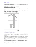
Fig. 22

  shows  the proper flue gas connection with additional air equipment. Observe the following during 

the installation of the flue gas connection:

• Install a flue pipe connection with an inspection aperture for cleaning

Install a flue pipe connection with an inspection aperture for cleaning.

• Fasten the flue gas connector piece to the boiler.

• Feed  the  connector into the flue  gas  system on a short,  ascending path.  Avoid  deflections, especially 

those with an angle of 90°.

• Fasten and support connectors sufficiently.

• Since the  flue  pipe  is only   fixed into the  flue gas  system and push-fitted  onto the boiler flue socket, it 

should be fitted very carefully so that it does not come loose.

• Only use parts of non-flammable materials for the flue gas system.

                                         fig.22

Chimneys and Chimney Connection Warnings

A sufficient flue draft of the flue gas system is the basic requirement for the correct functioning of the boiler.

It  fundamentally  affects  its performance  and  efficiency.  Therefore,  heed the  following  for  the flue gas 

connection:

• Please note that the boiler must be connected to the flue gas system in accordance with the relevant local

• Building code regulations, manufacture’s instructions and in consultation with an approved flue installer.

• The boiler may only be connected to a flue gas system with proper flue draft  ( technical spec. table).

Th

di

i

l

l i

f h fl

h

b b

d

h fl

fl

i

• The  dimension calculations of the flue gas path must be based on the flue gas mass-flow rate at maximum

rated output. 

• The effective chimney flue height is measured from the point of entry of the flue pipe into the chimney.

• Ensure  that the  calculation of the flue gas path and the connection of the flue  gas system is only carried 

out by qualified personnel.

• If a wrong boiler chimney is connected, the warranty is not valid.

24

Summary of Contents for S.MAX Series

Page 1: ...S MAX SERIES SOLID FUEL BOILER S MAX SERIES SOLID FUEL BOILER 0 S MAX REV 01 2010 0036 0036...

Page 2: ...fire 12 Setting outlet water temperature 13 Stoking 13 Overnight heating mode 13 Removing solid combustion residuals 13 Dewing and tarring 14 Boiler shutdown 14 Short term shutdown 14 Long term shutd...

Page 3: ...Information on the boiler plate The boiler Serial No is shown on the plate which is attached to the cover panel of the cast iron body 2...

Page 4: ...Boiler dimensions Boiler packaging dimensions 3...

Page 5: ...Technical parameters 4...

Page 6: ...ted equipment 6 The service technician putting the boiler into operation for the first time must show the user the various parts of the boiler and how to control the boiler with the boiler safety elem...

Page 7: ...d up with ice do not attempt to start up the boiler until normal operating conditions have been restored Ensuring safety of equipment and people The boiler and all accessories complies with the requir...

Page 8: ...d with necessary pipe sections for water connection It also has brackets for fitting thermostat sensors and brackets on feet for fastening the boiler to the base Attached to the cast iron boiler body...

Page 9: ...utlet from the boiler cast iron body It detects temperature of the hot water and regulates the supply of primary combustion air to underneath the boiler stoker by opening or shutting a flap situated i...

Page 10: ...Fig 7 Keep object s away from regulation hatch s front and channels for allowing primary air o t a d c a e s o a o g p a y a transfer Supply of secondary combustion air is controlled by an air rosett...

Page 11: ...ows the indications for inlet and drain shown on the valve must be followed Maximum temperature of the input water for temperature safety valve is 15 C and minimum water pressure Maximum temperature o...

Page 12: ...Check Valve 6 Four Way Mixing Valve 7 System Pump 8 Heating System 9 Open Expansion Tank Open type expansion tank must be equipped with the highest level in the entire hydraulic system The expansion...

Page 13: ...em water at the rate of 15 Please note The failure to meet this requirement may lead to the heat exchanger getting clogged up and the cast iron block may crack as a result During the heating season a...

Page 14: ...e boiler outlet is controlled Stoking First shut the regulating hatch this will shut supply of combustion air into the boiler Then open the chimney flap completely Partially open the stoking door and...

Page 15: ...hutting the boiler down clean it remove all combustion residuals empty the ashtray clean the stoking door contact surfaces and the ash compartment and then shut the boiler s stoking door and ash compa...

Page 16: ...ning and closing Boiler burning room and possible soot layers on smoke channels are checks and cleanings Boiler cleaning Wh th b il i d t d fi h l t th b il ll i l h t h ib Sensor of the pressure test...

Page 17: ...fig 12 fig 13 fig 14 fig 15 16...

Page 18: ...eating systems with gauge pressure up to 400 kPa which use water that meets the requirements of related standarts under no circumstances may the water be acidic i e it must have pH 7 and it should hav...

Page 19: ...om cellar corridor and in habitable rooms The room in which the boiler is located must have a permanent supply of air necessary for the combustion process The air must be free of halogen hydrocarbons...

Page 20: ...r room and allow manipulations with the boiler such as cleaning and stoking The distance between the front of the boiler and the wall should be at least the boiler length L plus 500 mm Minimum distanc...

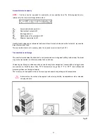
Page 21: ...nto the back section Screw the flue adapter with smoke flap onto the boiler combustion gases outlet Put a flue over the flue adapter and insert it into the chimney connection hole The flue diameter is...

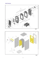
Page 22: ...SMAX boiler parts fi 18 fig 18 fig 19 21...

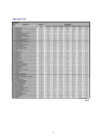
Page 23: ...Spare parts list p p fig 20 22...

Page 24: ...ss than 300 L Transportation and storage The manufacturer handles the boiler that is on a palette and secured against shifting with screws The boiler may not be transported in a different position tha...

Page 25: ...arnings A sufficient flue draft of the flue gas system is the basic requirement for the correct functioning of the boiler It fundamentally affects its performance and efficiency Therefore heed the fol...

Page 26: ...combustion products and the outside atmosphere We recommend the use of a chimney liner Have precise calculations carried out by a heating engineer or flue installer Coefficent 0 041 for wood Coeffice...

Page 27: ...Address Ikitelli Organize Sanayi Bolgesi Ataturk Bulvari 17 Cad No 5 ISTANBUL TURKEY Phone 90 212 485 48 74 Fax 90 212 485 48 73 Web www rima com tr e mail info rima com tr www onmetal com tr...

Reviews: