background image

10 Product Specifications


10-1. List of specifications 


- 53 -


<TIIS Specifications> 

Model SD-1DEC 
Detection principle 

Electrochemical method 

Detectable gas 

H2S/CO 

Gas concentration 
display 

LED(4digits

7segments) 

Measuring range 

H2S

0 - 30ppm or 0 - 50ppm or 0 - 100ppm 

CO

0 - 75ppm or 0 - 150ppm or 0 - 200ppm or 0 - 250ppm or 0 - 300ppm 

Resolution 

Depend on measuring range 

Detection method 

Suction method(pour into by external unit) 

Suction flow 

1.5±0.1L/min 

Alarm preset point 

Depend on Detectable gas 

Power indication 

POWER lamp lighting(green) 

Output 

Gas concentration signal 
Alarm contact(Gas alarm or Trouble alarm or Gas

Trouble common alarm) 

Alarm accuracy 

(under an identical condition) 

Less than ±30% to the alarm setpoint value 

Alarm-delay time 

(under an identical condition) 

Less than 30sec(when introducing 1.6 times thicker gas than alarm preset point)(without 
piping delay time) 

Gas alarm type 

Single alarm(H) 

Gas alarm indication 

ALM lamp lighting(red) 

Gas alarm action 

Auto-recover 

Trouble alarm

Self 

diagnosis 

System failure/Sensor failure 

Trouble alarm indication  FAULT lamp lighting(yellow)/content display 
Trouble alarm action 

Auto-recover 

Alarm contact 

No-voltage contact 1a 
Non-exciting at normal(exciting at alarm) or exciting at normal(non-exciting at alarm) 

Contact capacity 

250VAC - 0.5A/30VDC - 0.5A(resistive load) 

Transmission scheme 

Three-wire analog transmission 
(in common with power supply<power supply,signal,common>) 

Specification of 
transmission 

4 - 20mA DC (linear/load resistance less than 300

Ω

Transmission cable 

CVVS1.25 mm

2

 or 2.0mm

2

    - 3-core(when the contact is not used) 

CVVS1.25 mm

2

 or 2.0mm

2

    - 5-core(when the contact is used) 

Transmission distance 

Less than 1.25km in case of CVVS 1.25mm

2


Less than 2.0km in case of CVVS 2.0mm

2


Power supply 

24 VDC±10% 

Power consumption 

MAX.1.1W 

Cabling port 

Flame proof packing method<G3/4>(Compatible cables 

φ

9.6

13.0mm in outer 

diameter ) 

Piping port 

Rc1/8(with PP elbow union for O.D

φ

6-1t

PTFE pipe) 

Initial clear 

Approx.25sec 

Operating temperature 

-10 - +40

(non-rapidly-vary) 

Operating humidity 

30 - 80%RH(non-condensing) 

Structure 

Wall mounting type 

Explosion-proof 
structure 

Flame proof structure 

Explosion-proof grade 

Ex d 

C T6 X(TIIS<Japan>) 

Outer dimension 

Approx.148(W)×200(H)×88(D)mm(projection excluding) 

Weight Approx.2.6kg 
Color Munsell 

7.5BG5/2 


Summary of Contents for SD-1DEC

Page 1: ...PT2E 1789 Smart Transmitter Gas Detector Head SD 1DEC Operating Manual PT2E 178 PT2 178...

Page 2: ...reshold limit value may trigger a false alarm 3 This is a safety unit not a control unit The alarm contact output of the detector must be used for an external alarm lamp buzzer while the analog signal...

Page 3: ...ow to tube 23 5 How to Operate 24 5 1 Preparation for start up 24 5 2 Basic operating procedures 24 5 3 How to start the gas detector 25 5 4 Modes 26 5 5 Maintenance Mode User 27 5 6 How to exit 29 6...

Page 4: ...the gas concentration is over the setting value The detector is a safety unit not an analyzer or densitometer which performs quantitative qualitative analysis measurement for gases Please fully under...

Page 5: ...ase confirm the detector specification before using Please refer Declaration of Conformity that is at the end of this manual if you have CE marking type You can confirm instrument specification to see...

Page 6: ......

Page 7: ......

Page 8: ......

Page 9: ......

Page 10: ......

Page 11: ...ct Components 9 3 Product Components 3 1 Main unit and standard accessories Main Unit including a cable gland or an adapter ATEX IECEx Specification TIIS Specification 3 1 Main unit and standard acces...

Page 12: ......

Page 13: ......

Page 14: ......

Page 15: ......

Page 16: ......

Page 17: ......

Page 18: ......

Page 19: ......

Page 20: ......

Page 21: ......

Page 22: ......

Page 23: ......

Page 24: ......

Page 25: ......

Page 26: ......

Page 27: ......

Page 28: ......

Page 29: ......

Page 30: ......

Page 31: ......

Page 32: ...se of over the detection range Over Scale is displayed on the LED Power Indicator Lamp POWER Green During operation this lights up continuously Alarm Indicator Lamp ALM Red This lights up when the ala...

Page 33: ...d Access the gas leak point equipped with a protective gear to avoid dangers caused by possibly remaining gases and check whether gases remain or not by using a portable gas detector Check that the po...

Page 34: ......

Page 35: ......

Page 36: ...adjustment after ensuring that no interference gases exist around it Flow rate check Check the flow rate to find abnormalities Filter check Check the dust filter for dust or clogging Alarm Test Inspe...

Page 37: ...ty or clogged dust filter Alarm Test Inspects the alarm circuit by using the alarm test function Checks the alarm lamps Checks ALM1 activation Checks the external alarm Checks the activation of the ex...

Page 38: ......

Page 39: ......

Page 40: ......

Page 41: ......

Page 42: ......

Page 43: ......

Page 44: ......

Page 45: ......

Page 46: ......

Page 47: ......

Page 48: ......

Page 49: ......

Page 50: ......

Page 51: ...rn off and restart the indicator alarm unit If such a symptom is observed frequently take appropriate measures to eliminate the noise Sensor abnormalities E 1 The sensor is not connected or improperly...

Page 52: ...mpletely Disturbance by noise Turn off and restart the detector If such a symptom is observed frequently take appropriate measures to eliminate the noise Sudden change in the environment When the envi...

Page 53: ...osis System failure Sensor failure Trouble alarm indication FAULT lamp lighting yellow content display Trouble alarm action Auto recover Alarm contact No voltage contact 1a Non exciting at normal exci...

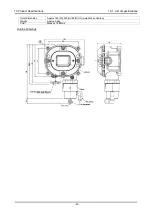
Page 54: ...10 Product Specifications 10 1 List of specifications 52 Outer dimension Approx 148 W 200 H 88 D mm projection excluding Weight Approx 2 6kg Color Munsell 7 5BG5 2 Outline Drawings...

Page 55: ...arm indication FAULT lamp lighting yellow content display Trouble alarm action Auto recover Alarm contact No voltage contact 1a Non exciting at normal exciting at alarm or exciting at normal non excit...

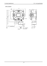
Page 56: ...10 Product Specifications 10 1 List of specifications 54 Outline Drawings...

Page 57: ......

Page 58: ...ction range ppm A concentration unit that means part per million of the combustible gas to be detected Calibration Adjusts the readings to the calibration gas concentration value by using the calibrat...

Page 59: ......

Reviews: