Riken Keiki SD-1DEC Operating Manual Download Page 52

9 Troubleshooting


- 50 -


<Abnormalities of Readings> 

Symptoms Causes 

Actions 

The reading rises (drops) 
and it remains so. 

Drifting of sensor 
output 

Perform zero adjustment. 

Presence of 
interference gas 

Disturbances by interference gases, such as solvents, 
cannot be eliminated completely. 

Slow leak 

A very small amount of the gas to be detected may be 
leaking (slow leak). Because ignoring it may cause 
dangers, take a remedial measure, i.e., taking actions the 
same as those for the gas alarm. 

Environmental 
changes 

Perform the zero adjustment (AIR adjustment). 

A gas alarm is triggered 
despite of no gas leak 
and no other 
abnormalities at the 
detection point. 

Presence of 
interference gas 

Disturbances by interference gases, such as solvents, 
cannot be eliminated completely. 

Disturbance by noise 

Turn off and restart the detector.   
If such a symptom is observed frequently, 
take appropriate measures to eliminate the noise. 

Sudden change in 
the environment 

When the environment (temperature etc.) changes 
suddenly, the detector cannot adjust to it and is affected 
by it. 
In some cases, the detector triggers an indication alarm.   
Because the detector cannot be used under sudden and 
frequent environmental changes, any preventive actions 
to eliminate them should be taken by the user. 

Slow response 

Clogged dust filter 

Replace the dust filter. 

Bended, clogged, 
or leaked suction 
tube or exhaust 
tube 

Fix the defective parts. 

Condensation is 
formed inside the 
suction tube. 

Fix the defective parts. 

Deteriorated sensor 
sensitivity 

Replace the sensor with a new one. 

Span adjustment 
impossible 

Improper calibration 
gas concentration 

Use the proper calibration gas. 

Deteriorated sensor 
sensitivity 

Replace the sensor with a new one. 


Summary of Contents for SD-1DEC

Page 1: ...PT2E 1789 Smart Transmitter Gas Detector Head SD 1DEC Operating Manual PT2E 178 PT2 178...

Page 2: ...reshold limit value may trigger a false alarm 3 This is a safety unit not a control unit The alarm contact output of the detector must be used for an external alarm lamp buzzer while the analog signal...

Page 3: ...ow to tube 23 5 How to Operate 24 5 1 Preparation for start up 24 5 2 Basic operating procedures 24 5 3 How to start the gas detector 25 5 4 Modes 26 5 5 Maintenance Mode User 27 5 6 How to exit 29 6...

Page 4: ...the gas concentration is over the setting value The detector is a safety unit not an analyzer or densitometer which performs quantitative qualitative analysis measurement for gases Please fully under...

Page 5: ...ase confirm the detector specification before using Please refer Declaration of Conformity that is at the end of this manual if you have CE marking type You can confirm instrument specification to see...

Page 6: ......

Page 7: ......

Page 8: ......

Page 9: ......

Page 10: ......

Page 11: ...ct Components 9 3 Product Components 3 1 Main unit and standard accessories Main Unit including a cable gland or an adapter ATEX IECEx Specification TIIS Specification 3 1 Main unit and standard acces...

Page 12: ......

Page 13: ......

Page 14: ......

Page 15: ......

Page 16: ......

Page 17: ......

Page 18: ......

Page 19: ......

Page 20: ......

Page 21: ......

Page 22: ......

Page 23: ......

Page 24: ......

Page 25: ......

Page 26: ......

Page 27: ......

Page 28: ......

Page 29: ......

Page 30: ......

Page 31: ......

Page 32: ...se of over the detection range Over Scale is displayed on the LED Power Indicator Lamp POWER Green During operation this lights up continuously Alarm Indicator Lamp ALM Red This lights up when the ala...

Page 33: ...d Access the gas leak point equipped with a protective gear to avoid dangers caused by possibly remaining gases and check whether gases remain or not by using a portable gas detector Check that the po...

Page 34: ......

Page 35: ......

Page 36: ...adjustment after ensuring that no interference gases exist around it Flow rate check Check the flow rate to find abnormalities Filter check Check the dust filter for dust or clogging Alarm Test Inspe...

Page 37: ...ty or clogged dust filter Alarm Test Inspects the alarm circuit by using the alarm test function Checks the alarm lamps Checks ALM1 activation Checks the external alarm Checks the activation of the ex...

Page 38: ......

Page 39: ......

Page 40: ......

Page 41: ......

Page 42: ......

Page 43: ......

Page 44: ......

Page 45: ......

Page 46: ......

Page 47: ......

Page 48: ......

Page 49: ......

Page 50: ......

Page 51: ...rn off and restart the indicator alarm unit If such a symptom is observed frequently take appropriate measures to eliminate the noise Sensor abnormalities E 1 The sensor is not connected or improperly...

Page 52: ...mpletely Disturbance by noise Turn off and restart the detector If such a symptom is observed frequently take appropriate measures to eliminate the noise Sudden change in the environment When the envi...

Page 53: ...osis System failure Sensor failure Trouble alarm indication FAULT lamp lighting yellow content display Trouble alarm action Auto recover Alarm contact No voltage contact 1a Non exciting at normal exci...

Page 54: ...10 Product Specifications 10 1 List of specifications 52 Outer dimension Approx 148 W 200 H 88 D mm projection excluding Weight Approx 2 6kg Color Munsell 7 5BG5 2 Outline Drawings...

Page 55: ...arm indication FAULT lamp lighting yellow content display Trouble alarm action Auto recover Alarm contact No voltage contact 1a Non exciting at normal exciting at alarm or exciting at normal non excit...

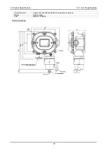
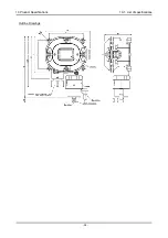
Page 56: ...10 Product Specifications 10 1 List of specifications 54 Outline Drawings...

Page 57: ......

Page 58: ...ction range ppm A concentration unit that means part per million of the combustible gas to be detected Calibration Adjusts the readings to the calibration gas concentration value by using the calibrat...

Page 59: ......

Reviews: