background image

  19 


ME12044A


6.6


Switching the Measurement Mode  

EXAFS is normally measured by the transmission method. However, in cases in which the sample in 
question makes it difficult to conduct measurement by the transmission method, such as when the 
sample is a film formed on a substrate which is opaque to X-rays or a diluted sample, or when 
elements composing the sample other than the object element cause heavy absorption, an EXAFS 
spectrum can sometimes be obtained by measuring the Fluorescence Yield (FY). The Looper allows 
measurement to be conducted in fluorescence mode when the counter arm is swung up by 90 degrees. 
The relevant procedure will be described below. 


Figure 6.16  Transmission Mode (Normal Setup) (D030328A04) 

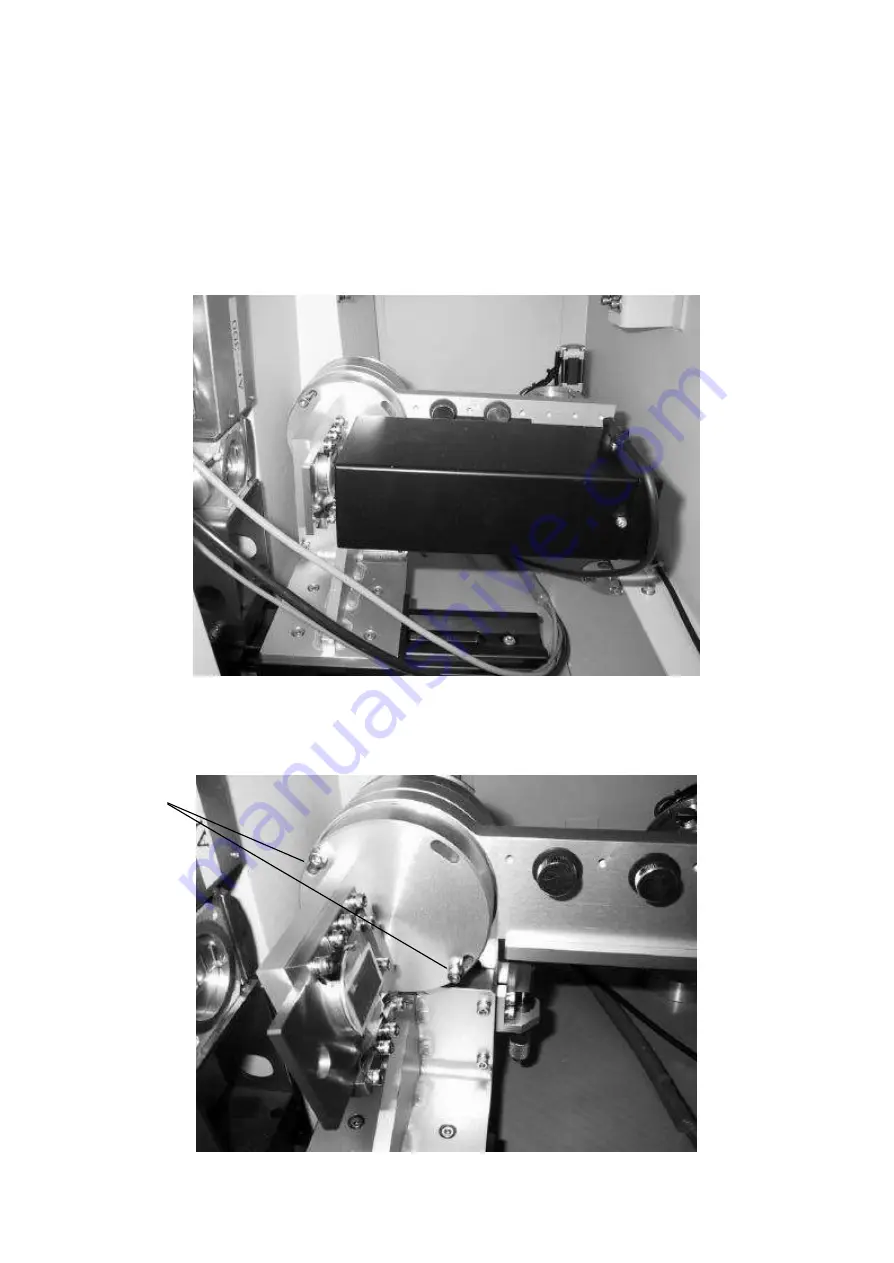
First, loosen the screws fastening the sample holder, and rotate it counterclockwise. When the sample 
holder is fully rotated within the slotted hole, it is situated at a point inclined by 10 degrees from its 
vertical position with respect to the beam.   


Figure 6.17  Sample Inclined by 10 Degrees (D030328A05) 

Fixing 
screws 

Summary of Contents for R-XAS

Page 1: ...Cat No 2170L101 L102 R XAS Looper Instruction Manual Manual No ME12044A02...

Page 2: ...s manual described in it may not be disclosed to a third party or copied in whole or in part without the written consent of Rigaku 2 As a rule one set of the instruction manual has to be purchased for...

Page 3: ...11 6 5 1 Installing the analyzing crystal 11 6 5 2 Moving the goniometer 11 6 5 3 Setting the detector provisionally 12 6 5 4 Setting the slits 12 6 5 5 Adjusting the monochromator 13 6 5 6 Adjusting...

Page 4: ...ME12044A ii First Edition May 27 2003 Second Edition May 27 2003...

Page 5: ...ich can be further divided into an X ray Absorption Near Edge Structure XANES observed near the absorption edge and an Extended X ray Absorption Fine Structure EXAFS observed along approximately 1 keV...

Page 6: ...hat performs spectrometry and collection simultaneously using a Johann type or Johannson type curved crystal In Figure 2 1 S is an X ray source A the center of the monochromator crystal and F a receiv...

Page 7: ...ray generator spectrometer goniometer divergence slit receiving slit and monochromator Figure 3 2 The X ray generator is a fixed target tube of 3 kW The spectrometer adopts the so called Linear spectr...

Page 8: ...vides linearity of up to 1 million cps through combined use with a high speed electronic circuit On the other hand the intensity monitor I detector for X rays transmitted through the sample employs a...

Page 9: ...ic Circuit Section 1 Proportional counter S PC I0 Incident X ray intensity detection a Amplifier Fixed gain b High voltage power supply and pulse height analyzer HV PHA i Lower level 0 to 5 V ii Upper...

Page 10: ...1 fastening the monochromator to the spectrometer and detach the monochromator In that operation the Insulock ties that clamp the cable to the monochromator may have to be cut off in some cases Exerci...

Page 11: ...alling the Optical axis Adjustment Slit D010524A07 Figure 5 4 View with the X ray Intensity Monitor Installed D010524A08 D030328A01 D030328A02 Figure 5 5 View with the SC Installed Using an X ray Inte...

Page 12: ...ontrol software Select init and click on OK to activate the initialization Enter the value of 0 05 select move and click on OK Figure 5 6 Figure 5 6 DS Setup Screen 5 2 2 Model with a direct beam moni...

Page 13: ...easure the intensity of the direct beam Select the FT tab in the Counter dialog box and set the FT time to 0 5 sec and the FT cycle number to 300 then click on OK This will start the measurement Use t...

Page 14: ...the axis Initially scan the entire range 3 to 3 in steps of 0 01 If a peak is found scan the range of 0 1 with that peak in the center in steps of 0 001 and set the axis to the peak position 6 3 Adju...

Page 15: ...ined by a magnet If the current setting in the control software is not Ge 220 choose Ge 220 after selecting Setup Crystal Figure 6 1 Ge 220 D030328A03 6 5 2 Moving the goniometer Move the goniometer t...

Page 16: ...t the monochromator crystal Initialize the I0 detector Select Adjust I0 Counter enter HV 1050 Base line 0 5 Window 3 and click on OK Figure 6 3 Detector Setup Screen 6 5 4 Setting the slits Set the di...

Page 17: ...at the X rays emitted from the X ray generator are led to the sample section Figure 6 5 Adjust Menu Select Adjust Monochromator in the main menu Figure 6 6 Monochromator Adjustment Dialog Box Specify...

Page 18: ...ometer set the Z axis using the absorption edge The procedure for doing so is as follows load the standard sample such as metal foil into the sample holder and set the goniometer to the energy of the...

Page 19: ...ing the center by fitting the peak by a quadratic curve and prompting selection of whether to move to that position Clicking on OK again here moves you to the position determined through calculation A...

Page 20: ...alyzer to the specified value and gradually vary the voltage imposed on the detector This will change the gain of the detector and bring the pulse hight of the output signal to within the range of the...

Page 21: ...ase of the proportional counter a small escape peak will appear immediately before the main peak Be sure to define the range without that peak 3 Setup of HV PHA The values found in the HV scan and PHA...

Page 22: ...to be made Select Measure Execute the measurement conditions will be displayed Select Cu in the Conditions area and click on Measure The measurement will begin If a file of the same name already exis...

Page 23: ...an EXAFS spectrum can sometimes be obtained by measuring the Fluorescence Yield FY The Looper allows measurement to be conducted in fluorescence mode when the counter arm is swung up by 90 degrees The...

Page 24: ...far as it will go Figure 6 18 Swinging up the Counter Arm by 90 Degrees D030328A06 Finally install the scintillation counter If the connector of the scintillation counter interferes with the wall loo...

Page 25: ...ounter arm assembly can be raised or lowered using the micrometer shown in Figure 6 20 Use this micrometer to adjust the position of the sample Figure 6 20 Micrometer for Vertical Adjustment of a Samp...

Page 26: ...ill be out of the scope of the warranty 1 Those caused by fire or natural disaster 2 Those caused by failure to use the equipment as stipulated in the contract equipment used for a purpose other than...

Page 27: ...gh voltage To replace them disconnect the cables after switching off the controller 6 The I0 detector employs a thin Beryllium window Exercise caution as it may be broken if touched by hand or struck...

Page 28: ...ely delicate When it is not used store it in a desiccator or similar device 2 When the I0 detector is not used store it in a desiccator or similar device 3 The sliders and ball screws should be grease...

Page 29: ...y that the detector has not yet been initialized Choose the HV HPA tab by selecting Adjust I Counter I0 Counter in the control software MexWin and initialize the detector Check to make sure the cable...

Page 30: ...e conditions Moreover if the changer is loaded with a sample in a single position and that position is switched with a position not loaded with any sample the changer will allow measurement Set reset...

Page 31: ...mple changer main unit is erected as illustrated in Figure 11 2 Figure 11 3 shows the changer with the turret mounted In this condition slide the turret sideways along the groove with Sample No 1 posi...

Page 32: ...on OK Figure 11 5 Software Setup 11 4 2 Operation Figure 11 6 Manual Operation The sample holders are operated by Manual Sample Change init initializes the sample changer Immediately after installing...

Page 33: ...e 11 7 will be invoked Clicking on Sample changer conditions on this screen will open an input dialog box for sample changer conditions Enter the file name sample name and comments there The sample wi...

Page 34: ...alternately in the beam position and measure the EXAFS spectrum by defining the I detector output of sample No 1 as I0 and the I detector output of sample No 2 as I As this mode measures EXAFS using...

Page 35: ...fferential Scanning Calorimeters Specifictions Subject to Change without Notice RIGAKU International Corporation 3 9 12 Matsubara cho Akishima shi Tokyo 196 8666 Japan Phone 81 42 545 8189 Fax 81 42 5...

Page 36: ...Telex J26418 RINT http www rigaku com...

Reviews: