


20141167
16
GB
Installation
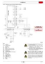
5.7
Combustion head adjustment
The combustion head leaves the factory set for the minimum
output.
Ignition must be carried out at reduced power and not
exceeding 120 kW.
In order to measure the ignition output:
–
disconnect the connector (
CN1
) on the ionisation probe cable
(see electrical connections on page 7)
; the burner will fire and
then go into lockout after the safety time has elapsed (3s).
–
Perform 10 ignitions with consecutive lockouts.
–
Read the total quantity of gas burned on the meter. This
quantity must be equal to or less than:
–
0.10 Nm
3
for G20 (natural gas H);
–
0.10 Nm
3
for G25 (natural gas L);
–
0.03 Nm
3
for G31 (LPG).
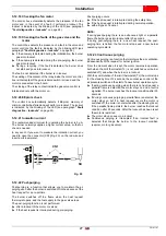
The adjustment of the combustion head varies depending on the
burner output.
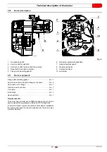
This is carried out by turning the adjustment screw 6)(Fig. 11)
clockwise or anti-clockwise until the notch on the regulating rod
2) lines up with the outside surface of the head assembly 1).
Fig. 11 shows the head regulating rod set on notch 4.
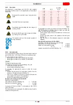
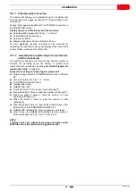
Example
The diagram (Fig. 12) is indicative and shows the calibration of
the combustion head in relation to the burnt output.
To ensure the burner works efficiently, we suggest adjusting the
combustion head according to the requirements of the specific
boiler.
The burner is installed in a 210 kW boiler. Considering an
efficiency of 90%, the burner must supply around 230 kW; for this
burner output the adjustment should be on notch 4.
5.7.1
Removing the head assembly
To remove the head assembly (Fig. 11) it is necessary to:
disconnect the connections 3) and 5);
remove the small tube 4) and loosen the screws 10);
loosen and remove the screws (7), remove the head holder
assembly (1) by slightly rotating it to the right.
5.7.2
Reassembling the head assembly
Reassemble with the reverse procedure to that described above,
repositioning the head assembly 1)(Fig. 11) as it was originally.
CAUTION
Take care not to change the setting position on
the elbow-bracket (2) when dismantling.
CAUTION
Screw in the screws 7)(Fig. 11) all the way without
locking them. Lock them with a tightening torque
of 3 - 4 Nm.
ATTENTION
Check that when operating there are no gas leaks
from the screw housings.
Should the pressure test point 11)(Fig. 11)
become accidentally loose, we recommend to
correctly fasten it checking that hole (F)(Fig. 11)
placed on the inner side of the head assembly
1)(Fig. 11) is facing downwards.
Fig. 11
S7801
Fig. 12
Notch
210.000
150.000
290.000
190.000
170.000
130.000
kcal/h
kW
0
8
2
4
6
150
190
210
250
270
290
310
330
170
230
350
10
D6235
230.000
250.000
270.000


