background image

20049577

10 

GB

Technical description of the burner

3.7

Minimum furnace dimensions

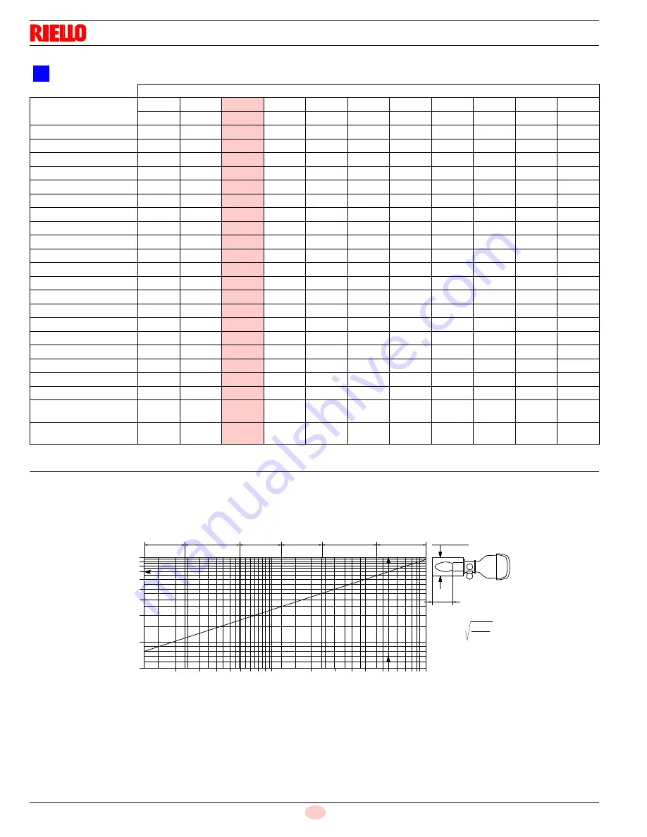
The firing rate was obtained in special test boilers. 

Fig. 4 indicates the diameter and length of the test combustion
chamber.

Example:

Output 26510 Mbtu/hr: - diameter 47.7 inch - length 20 ft.

CORRECTED BURNER AIR PRESSURE ACCORDING TO ALTITUDE

Altitude

Rated Pressure

m a.s.l.

0

100

305

610

915

1220

1525

1830

2135

2440

ft a.s.l

0

328

1000

2000

3000

4000

5000

6000

7000

8000

0.50

0.49

0.50

0.51

0.53

0.55

0.57

0.59

0.62

0.64

0.67

1.00

0.99

1.00

1.02

1.06

1.10

1.14

1.19

1.23

1.28

1.34

1.50

1.48

1.50

1.53

1.59

1.65

1.71

1.78

1.85

1.92

2.01

2.00

1.97

2.00

2.05

2.12

2.20

2.28

2.37

2.46

2.56

2.67

2.50

2.47

2.50

2.56

2.65

2.75

2.85

2.96

3.08

3.21

3.34

3.00

2.96

3.00

3.07

3.18

3.30

3.43

3.56

3.70

3.85

4.01

3.50

3.46

3.50

3.58

3.71

3.85

4.00

4.15

4.31

4.49

4.68

4.00

3.95

4.00

4.09

4.24

4.40

4.57

4.74

4.93

5.13

5.35

4.50

4.44

4.50

4.60

4.77

4.95

5.14

5.33

5.54

5.77

6.02

5.00

4.94

5.00

5.12

5.30

5.51

5.71

5.93

6.16

6.41

6.69

5.50

5.43

5.50

5.63

5.83

6.06

6.28

6.52

6.77

7.05

7.35

6.00

5.92

6.00

6.14

6.36

6.61

6.85

7.11

7.39

7.69

8.02

6.50

6.42

6.50

6.65

6.89

7.16

7.42

7.71

8.01

8.34

8.69

7.00

6.91

7.00

7.16

7.42

7.71

7.99

8.30

8.62

8.98

9.36

7.50

7.40

7.50

7.67

7.96

8.26

8.56

8.89

9.24

9.62

10.03

8.00

7.90

8.00

8.18

8.49

8.81

9.13

9.48

9.85

10.26

10.70

8.50

8.39

8.50

8.70

9.02

9.36

9.71

10.08

10.47

10.90

11.37

9.00

8.88

9.00

9.21

9.55

9.91

10.28

10.67

11.09

11.54

12.04

9.50

9.38

9.50

9.72

10.08

10.46

10.85

11.26

11.70

12.18

12.70

10.00

9.87

10.00

10.23

10.61

11.01

11.42

11.86

12.32

12.82

13.37

Average barometric

pressure (20°C)

mbar

1013

1000

977.4

942.8

908.2

875.8

843.5

811.85

779.8

747.8

Average barometric

pressure (68°F)

"w.c.

399

394

385

371

358

345

332

320

307

294

2

Fig. 4


1000

MBtu/hr760

1.5

7.5 11.3 18.9

37870

1.6

3.3

6.6

9.9

13.2

16.5

29.6

23.0

1 5 . 7

1 9 . 7

2 3 . 6

3 1 . 5

3 9 . 4

4 7 . 2

i n c h es

f t

ft= 0,12 MBtu

hr

22.7

D9084

Summary of Contents for RS 1200/E BIOGAS/GPL C01 FS2

Page 1: ...20049577 2 07 2012 Installation use and maintenance instructions Forced draught gas burner Modulating operation Code Model 20048377 RS 1200 E BIOGAS GPL C01 FS2 GB ...

Page 2: ......

Page 3: ...2 3 11 Control box for the air fuel ratio LMV51 13 3 12 Servomotor SQM48 4 15 4 Installation 16 4 1 Notes on safety for the installation 16 4 2 Handling 16 4 3 Preliminary checks 16 4 4 Operating position 17 4 5 Securing the burner to the boiler 17 4 5 1 Boring the boiler plate 17 4 6 Blast tube length 17 4 7 Burner securing 18 4 8 Accessibility to the interior of the combustion head 18 4 9 Gas tr...

Page 4: ...26 5 6 Final checks with burner operating 27 6 Maintenance 28 6 1 Notes on safety for the maintenance 28 6 2 Maintenance programme 28 6 2 1 Maintenance frequency 28 6 2 2 Checking and cleaning 28 6 3 Opening the burner 29 6 4 Closing the burner 29 7 Faults Probable causes Solutions 30 A Appendix Spare parts 31 B Appendix Accessories 34 C Appendix Burner start up report 35 ...

Page 5: ...car ried out correctly may cause damage to the ma chine and or injury to people DANGER DANGER LIVE COMPONENTS This symbol indicates operations which if not car ried out correctly lead to electric shocks with lethal consequences DANGER FLAMMABLE MATERIAL This symbol indicates the presence of flammable materials DANGER BURNING This symbol indicates the risks of burns due to high temperatures DANGER ...

Page 6: ... of damage to things or injury to peo ple if such damage injury was due to any of the following causes incorrect installation start up use and maintenance of the burner improper incorrect or unreasonable use of the burner intervention of unqualified personnel carrying out of unauthorised modifications on the equipment use of the burner with safety devices that are faulty incorrectly applied and or...

Page 7: ...nance Only those parts envisaged by the manufacturer can be replaced 2 2 Personnel training The user is the person body or company that has acquired the ma chine and intends to use it for the specific purpose He is responsi ble for the machine and for the training of the people working around it The user undertakes to entrust the machine exclusively to suitably trained and qualified personnel unde...

Page 8: ...ax kW MBtu hr 5500 12000 18766 40944 min kW MBtu hr 1500 5118 Fuel max delivery pressure at max delivery 2 SCFH wc Natural gas 29973 17 9 Operation Low high or modulating Standard applications Boilers water steam thermal oil Ambient temperature F 32 104 0 40 C Combustion air temperature F max 140 60 C Noise levels 3 dBA 99 Fan motor IE2 Control circuit power supply V Ph Hz 120 1 60 Main power supp...

Page 9: ...erall dimensions The maximum dimensions of the burner are given in Fig 2 Bear in mind that inspection of the combustion head requires the burner to be opened by rotating the rear part on the hinge The overall dimensions of the burner when open are indicated by L and R Tab E inch A B C lbs RS 1200 E C01 96 1 16 63 37 64 56 11 16 1100 D36 Fig 1 inch A B C D E F G H I L R S RS 1200 E C01 61 21 32 20 ...

Page 10: ...dia gram Minimum output must not be lower than the minimum limit shown in the diagram WARNING The firing rate was obtained considering a room temperature of 68 F and an atmospheric pressure of 394 wc approx 0 ft above sea level with the combustion head adjusted wc Burner power output Combustion chamber pressure Fig 3 20050769 ...

Page 11: ...Capacity m a s l 0 100 305 610 915 1220 1525 1830 2135 2440 ft a s l 0 328 1000 2000 3000 4000 5000 6000 7000 8000 500 494 500 512 530 551 571 593 616 641 669 1000 987 1000 1023 1061 1101 1142 1186 1232 1282 1337 1500 1481 1500 1535 1591 1652 1713 1778 1848 1924 2006 2000 1974 2000 2046 2121 2202 2284 2371 2464 2565 2675 2500 2468 2500 2558 2652 2753 2855 2964 3079 3206 3343 3000 2962 3000 3069 31...

Page 12: ...09 4 24 4 40 4 57 4 74 4 93 5 13 5 35 4 50 4 44 4 50 4 60 4 77 4 95 5 14 5 33 5 54 5 77 6 02 5 00 4 94 5 00 5 12 5 30 5 51 5 71 5 93 6 16 6 41 6 69 5 50 5 43 5 50 5 63 5 83 6 06 6 28 6 52 6 77 7 05 7 35 6 00 5 92 6 00 6 14 6 36 6 61 6 85 7 11 7 39 7 69 8 02 6 50 6 42 6 50 6 65 6 89 7 16 7 42 7 71 8 01 8 34 8 69 7 00 6 91 7 00 7 16 7 42 7 71 7 99 8 30 8 62 8 98 9 36 7 50 7 40 7 50 7 67 7 96 8 26 8 ...

Page 13: ...to boiler 14 Gas butterfly valve 15 Shutter 16 Lever for movement of combustion head 17 Tie rods for air damper movement 18 Air pressure switch 19 Air pressure test point 20 Ignition pilot attachment 21 UV fotocell holder 22 Hinge for opening burner 23 Air pressure test point pressure test point 24 Electric board protection 9 18 1 10 6 14 4 11 12 20 16 21 24 23 15 7 8 13 19 5 22 17 2 Fig 5 2005080...

Page 14: ...c joint for ignition cable 25 Electric joint for air pressure switch pipe 26 Free entrance for pilot gas train valves 27 Hole for fan motor cable 28 Plug socket for QRI flame sensor 29 Plug socket for air actuator 30 Plug socket for maximum pressure switch 31 Contactor with auxiliary contact for star delta start KL1 32 Holes for cables grommets for electrical wirings accessories and power supply t...

Page 15: ...ust also be observed Condensation and ingress of humidity must be avoided Should such conditions occur make sure that the unit will be completely dry before switching on again Static charges must be avoided since they can damage the unit s electronic components when touched Mechanical design The LMV5 is a microprocessor based burner management sys tem with matching system components for the contro...

Page 16: ...use externally Max 16 AT Undervoltage Safety shutdown from operating position at mains voltage Restart on rise in mains voltage AC 96 V AC 100 V Oil pump magnetic clutch nominal voltage Nominal current Power factor 1 6A cos 0 4 Air pressure switch test valve nominal voltage Nominal current Power factor 0 5A cos 0 4 Terminal loading Outputs Total contact loading Mains voltage Input current of unit ...

Page 17: ...voltage section The static torque is reduced when the electrical supply of the ac tuator is switched off The housing cover may only be removed for short periods of time for wiring or when making the addressing In similar cases make sure that dust or dirt does not penetrate inside the actu ator The actuator comprises a PCB with ESD sensitive compo nents The top side of the board carries a cover whi...

Page 18: ...ust be free from hazardous mixes e g chloride fluoride halogen if present it is highly recommended to carry out cleaning and maintenance more frequently WARNING The handling operations for the burner can be high ly dangerous if not carried out with the greatest at tention keep any unauthorised people at a distance check the integrity and suitableness of the available means of handling Check also t...

Page 19: ... blast tube 4 This protective fettling must not compromise the extraction of the blast tube For boilers having a water cooled front the refractory fettling 2 5 Fig 10 is not required unless it is expressly requested by the boiler manufacturer WARNING The burner is designed to operate only in positions 1 2 3 and 4 Fig 10 Installation 1 is preferable as it is the only one that allows the maintenance...

Page 20: ...e electrode Disconnect the tube of ignition pilot 4 Unscrew the screw 5 after removing the gas pressure switch 5 Fig 5 Extract the internal part 6 of the combustion head In case of replacement of biogas combustion head 6 with LPG combustion head use the nut and ogive from the con nector 59 page 31 supplied with the burner and install them on the new pilot tube After assembling the same combustion ...

Page 21: ...mbustion head open ing can be varied by moving the tie rod onto holes 5 6 7 Fig 15 When dealing with boilers featuring a strong back pressure if air delivery is insufficient even with the damper fully open you can use a different setting shows in the following table do this by moving the tie rod onto the next highest hole numerically speak ing thus increasing the combustion head s opening and henc...

Page 22: ...plosion danger due to fuel leaks in the presence of a flammable source Precautions avoid knocking attrition sparks and heat Make sure that the fuel interception tap is closed before performing any operation on the burner WARNING The fuel supply line must be installed by qualified personnel in compliance with current standards and laws M ai n gas suppl y 10 2 3 4 5 6 11 Vent Pi l ot gas suppl y 2 1...

Page 23: ...ification label and in this manual Do not invert the neutral with the phase in the electrical supply line Any inversion would cause a lockout due to firing failure The electrical safety of the device is obtained only when it is correctly connected to an efficient earthing system made according to current standards It is necessary to check this fundamental safety requirement In the event of doubt h...

Page 24: ...tor is 400V To reset in the case of an intervention of the thermal relay press the button RESET Fig 18 The button STOP Fig 18 opens the NC 95 96 contact and stops the motor To test the thermal relay insert a screwdriver in the window TEST Fig 19 and move it in the sense of the arrow towards right 4 13 2 Electronic thermal relay To reset in the case of an intervention of the thermal relay press the...

Page 25: ...049577 GB 4 14 Reversible direction WARNING If it is necessary to reverse the direction then reverse the two main supply phases For example L1 with L2 there is not difference between IE1 and IE2 Epact S8447 L1 L2 Fig 23 ...

Page 26: ...equipped with a pilot light that signals voltage passing through 5 3 Burner start up Close the local controls and position the selector 1 Fig 25 to LO CAL Make sure that the lights or testers connected to the solenoids or the pilot lights on the solenoids themselves indicate that no voltage is present If voltage is present stop the burner immediately and check the electrical connections When the l...

Page 27: ...ge of the air and fuel through positioning using direct servocommands of the relevant valves eliminating the possi ble play in the calibration systems with mechanical cam lever mechanisms used on traditional modulating burners 2 The modulation of the burner output in accordance with the load required by the system with maintenance of the pres sure or temperature of the boiler at the operating valu...

Page 28: ...reduce the adjustment pressure by slowly turning the adjustment dial anticlockwise until the burner locks out Then turn the dial clockwise by 0 8 WC and repeat burner firing If the burner locks out again turn the dial again clockwise by 0 4 WC 5 5 3 Minimum gas pressure switch Adjust the minimum gas pressure switch after having performed all the other burner adjustments with the pressure switch se...

Page 29: ...e mini mum end of scale position Turn the air pressure switch to the maximum end of scale position Æ The burner must stop in lockout Turn off the burner and cut off the power Disconnect the minimum gas pressure switch connector Æ The burner must not start Disconnect the ionisation probe wire Æ The burner must stop in lockout due to ignition failure WARNING Make sure that the mechanical locking sys...

Page 30: ...e signal s intensity is shown on the AZL display and operating unit Min value for a good work 3 5 Vdc AZL dosplay flame approx 50 If the value is lower it can depend on photocell positioned incorrectly low corrent lower than 96V bad regulation of the burner To measure power use a voltometer with a 10 Vdc scale connect ed as illustrated in Fig 29 Boiler Clean the boiler as indicated in its accompan...

Page 31: ...the appropriate card to record the new combustion values they will be useful for subsequent controls 6 3 Opening the burner Remove the tie rod 1 Fig 30 of the head movement lever undoing the nut 2 Disconnect the socket 4 of the gas servomotor Remove the screws 3 At this point it is possible to open the burner on the hinge 6 4 Closing the burner Refit following the steps described but in reverse or...

Page 32: ...nalled by the red burner lockout LED The display visualises alternately the lockout code and the relative diagnostic To reset the start up conditions refer to the Reset pro cedure indicated in the control box manual supplied When the burner starts again the red LED goes out and the control box is reset 7 Faults Probable causes Solutions ...

Page 33: ...ts 5 1 2 3 4 6 7 8 8 19 9 10 11 12 13 14 51 16 17 18 20 21 22 23 24 25 26 27 28 29 30 31 32 32 33 35 15 34 34 36 37 38 36 39 40 41 42 57 43 50 44 45 46 47 48 49 58 60 56 52 19 55 59 54 52 53 61 55 63 64 11 10 62 66 67 69 68 9 71 70 72 65 ...

Page 34: ...5 20014103 GAS PRESSURE SWITCH B 26 20039362 PROBE A 27 20032625 AIR DAMPER 28 20034046 SUPPORT ELECTRODE 29 3013253 GAS SERVOMOTOR B 30 3012956 TRANSFORMER 31 3013284 ELECTRONIC CAM TRASFORMER B 32 3020068 RELAY C 33 20010969 RELAY C 34 20043289 CONTROL BOX 35 3012841 CONTROL BOX 36 20036017 GREEN SIGNAL LIGHT A 37 20027020 YELLOW SIGNAL LIGHT A 38 20036019 WHITE SIGNAL LIGHT A 39 3013283 DISPLAY...

Page 35: ...010963 SWITCH C 58 3003935 CONTROL BOX 59 20014633 CONNECTOR C 60 20050144 FEEDER 61 3012782 RELAY C 62 20017231 DIFFUSER DISC A 63 20050435 ELECTRODE A 64 3012267 ELECTRODE CONNECTION A 65 20013969 AUXILIARY CONTACT C 66 3013158 TUBE 67 3013159 TUBE 68 20050438 CONTROL WHEEL 69 20050445 GAS DIFFUSER 70 20050447 GAS DIFFUSER 71 20050441 O RING B 72 20013967 AUXILIARY CONTACT C N CODE DESCRIPTION ...

Page 36: ...ppendix Accessories Burner Code RS 1200 E C01 3010388 Burner Code RS 1200 E C01 3010401 Parameter to be checked Probe Adjustment field Type Code Temperature 100 500 C PT 100 3010110 Pressure 0 2 5 bar 0 16 bar Output probe 4 20 mA 3010213 3010214 WARNING The installer is responsible for the supply and instal lation of any required safety device s not indicated in this manual ...

Page 37: ... Fire Main Power Supply O2 Low Fire High Fire Control Power Supply CO Low Fire High Fire Burner Firing Rate NOX Low Fire High Fire Manifold Pressure Net Stack Temp Low Fire High Fire Pilot Flame Signal Comb Efficiency Low Fire High Fire Low Fire Flame Signal Overfire Draft High Fire Flame Signal CONTROL SETTINGS Operating Setpoint Low Oil Pressure High Limit Setpoint High Oil Pressure Low Gas Pres...

Reviews: