


9
20085953
GB
Technical description of the burner
4.6
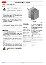
Maximum dimensions
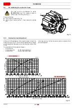
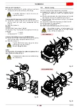
The dimensions of the burner are shown in Fig. 1.
Bear in mind that inspection of the combustion head requires the
burner to be opened and the rear part drawn back on the guides.
The dimensions of the open burner are indicated by position I.
Tab. E
4.7
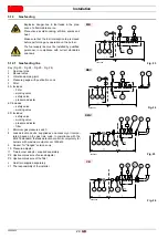
Firing rates
The
maximum output
is chosen within area A (and B for
RS 120/EV BLU) of the diagram (Fig. 2).
The
minimum output
must not be lower than the minimum limit
of the diagram.
Fig. 1
D1206
mm
A
B
C
D
E
F
G
H
I
L
M
N
O
RS 120/EV BLU
553
338
215
555
840
255
186
430
1161
214
134
221
2”
RS 160/EV BLU
681
366
315
555
872
373
222
430
1442
230
141
260
2”
RS 200/EV BLU
732
427
305
555
872
373
222
430
1442
230
141
260
2”
WARNING
to use area B (RS 120/EV BLU) as well, the pre-
calibration of the combustion head is necessary,
as explained in the paragraph
"Pre-calibrating
the combustion head"
on page 22.
CAUTION
The firing rate (Fig. 2) of the model
RS 200/EV
BLU
refers to the operation with fuel G20 - G25.
In case G31 is used, the minimum output goes
from 550 to 630 kW.
WARNING
The firing rate (Fig. 2) was obtained considering a
room temperature of 20°C and an atmospheric
pressure of 1013 mbar (approx. 0 m above sea
level), with the combustion head adjusted as
shown at 22.
Fig. 2
20086313
RS 200/EV BLU
RS 160/EV BLU
Thermal power
Thermal power
Thermal power
RS 120/EV BLU
Combustio
n
cha
m
ber
pressur
e
-
mb
a
r
Combustion chamber
pressure -
mb
ar
Combustion chamber
pressure -
mb
ar
Summary of Contents for RS 120/EV BLU
Page 2: ...Translation of the original instructions ...
Page 43: ...41 20085953 GB Appendix Electrical panel layout ...
Page 45: ...43 20085953 GB Appendix Electrical panel layout ...
Page 46: ...20085953 44 GB Appendix Electrical panel layout ...
Page 47: ...45 20085953 GB Appendix Electrical panel layout ...
Page 54: ......
Page 55: ......


