20123781
28
GB
Start-up, calibration and operation of the burner
6.4
Burner ignition
The burner should light after having performed the above steps.
If the motor starts up, but the flame does not appear and the con-
trol box goes into lockout, reset it and wait for a new ignition at-
tempt.
If ignition is still not achieved, it may be that gas is not reaching
the combustion head within the safety time period of 3 seconds;
In this case increase gas ignition delivery.
The arrival of gas at the sleeve is indicated by the U-type manom-
eter (Fig. 31).
If further burner lockouts occur, see the "Reset procedure" in the
control box's manual.
Once the burner has fired, now proceed with global calibration
operations.
Once regulations have been made, select the “
AUTOMATIC
”
mode on the display.
6.5
Combustion air adjustment
Fuel/combustion air synchronisation is done with the relevant
servomotors (air and gas) by logging a calibration curve by
means of the electronic cam.
It is advisable, to reduce the loss and for a wide calibration field,
to adjust the servomotors to the maximum of the output used, the
nearest possible to the maximum opening (90°).
On the gas butterfly valve, fuel step according to the burner out-
put required, with servomotor completely open, is carried out by
the pressure stabiliser placed on the gas train.
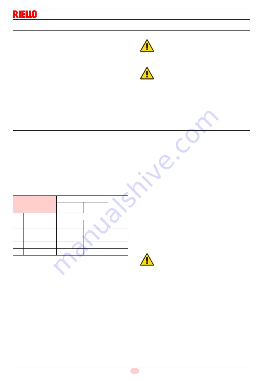
The values in Tab. K can be a reference for a good combustion
calibration.
Tab. K
6.5.1
Air / gas adjustment and output modulation
The air/gas regulator and output modulation system equipping
RS
series burners performs a number of integrated functions to
optimise burner function, in both individual installations and in
combination with other units (e.g. double furnace boiler or multi-
ple heat generators in parallel).
The basic system functions control:
1
The dosage of the air and fuel through positioning using
direct servo commands of the relevant valves eliminating
the possible play in the calibration systems with mechanical
cam lever mechanisms, used on traditional modulating
burners.
2
The modulation of the burner output in accordance with the
load required by the system, with maintenance of the pres-
sure or temperature of the boiler at the operating values set.
3
The sequence (cascade adjustment) of more than one
boiler through the suitable connection of the various units
and the activation of the internal software of the individual
systems (option).
Further interfaces and communication functions with computers,
for remote control or integration in central supervision systems
are available on the basis of the configuration of the system.
The first start-up and curve synchronisation manual is supplied
with the burner.
At request, the complete manual for the control and setting of all
parameters is available.
WARNING
In the event the burner stops, in order to prevent
any damage to the installation, do not unblock the
burner more than twice in a row. If the burner
locks out for a third time, contact the customer
service.
DANGER
In the event there are further lockouts or faults
with the burner, the maintenance interventions
must only be carried out by qualified, authorised
personnel, in accordance with the contents of this
manual and in compliance with the standards and
regulations of current laws.
EN 676
Air excess
CO
Max. output
1.2
Max. output
1.3
GAS
Theoretical max
CO
2
0 % O
2
CO
2
% Calibration
mg/kWh
= 1.2
= 1.3
G 20
11.7
9.7
9
1000
G 25
11.5
9.5
8.8
1000
G 30
14.0
11.6
10.7
1000
G 31
13.7
11.4
10.5
1000
WARNING
The first start up and every further internal setting
operation of the adjustment system or the expan-
sion of the base functions require access by
means of password and are to be carried out by
service personnel who are especially trained for
the internal programming of the instrument and
the specific application created with this burner.
Summary of Contents for RS 1000/EV BLU
Page 2: ...Translation of the original instructions ...
Page 41: ...39 20123781 GB Appendix Electrical panel layout ...
Page 43: ...41 20123781 GB Appendix Electrical panel layout 0 1 2 2 2 0 3 4 56 789 ...
Page 45: ...43 20123781 GB Appendix Electrical panel layout 0 1 0 1 222 3 3 3 4 3 3 3 3 3 3 3 3 3 3 3 4 3 ...
Page 47: ......