background image

HELIOTERM INVERTER

Doc-0079257 Rev. 1

B

A

IT

I morsetti a molla destinati alle connessioni elettriche 

accettano cavi rigidi o flessibili con sezione da 0,2 a 1,5 

mm², mentre se gli stessi sono dotati di capocorda con 

collare in plastica la sezione massima è ridotta a 0,75 

mm². Per una corretta e sicura connessione eseguire le 

seguenti operazioni:


Realizzare una spellatura di 8 mm di lunghezza come in 

figura a pagina seguente.


Se il cavo è rigido il terminale del filo entrerà agevolmente, 

mentre con cavo flessibile è consigliabile l’utilizzo di una 

pinza a becchi per un corretto inserimento.


Spingere a fondo i cavi e verificare il corretto fissaggio 

tirandoli leggermente.


Per scollegare i cavi premere con un cacciavite sul 

corrispondente dentino bianco (rif. C) ed estrarre il 

conduttore.

Connessioni morsetti a molla linea RS485 

(-AB+) e contatto presenza (CP)

Connessioni ingresso contatto presenza CP CP presence contact input connection

Alla chiusura del contatto collegato all’ingresso CP (rif. A) 

tutte le utenze vengono spente. Se il contatto è aperto 

l’unità è attiva, se il contatto è chiuso è disattivata e alla 

pressione di un tasto il simbolo   lampeggia.

When the contact connected to the CP (ref. A) input is 

closed all the users connected will be switched off. If the 

contact is open the unit is active, if the contact is closed 

the unit is deactivated an by pressing a key the symbol   

flashes.

EN

The spring terminals inteded for the electrical connections 

are compatible with 0,2 to 1,5 mm² section rigid or flexible 

cables, while if they are provided with lugs with plastic 

collar, their maximum section is reduced to 0,75 mm². 

For correct and secure connection follow the operations 

below:


Strip the cable by 8 mm as shown at next page.


If the cable is rigid you should be able to insert its end 

easily, while if it is flexible you should use a pair of nose 

grippers.


Insert the cables completely and makes sure they are 

properly fixed by pulling them slightly.


To disconnect the cables use a screwdriver to press 

the corresponding white notch (ref. C) and remove the 

conductor.

Connections line RS485 (-AB+) spring 

clamps and presence contact (CP)

Summary of Contents for CPD 35

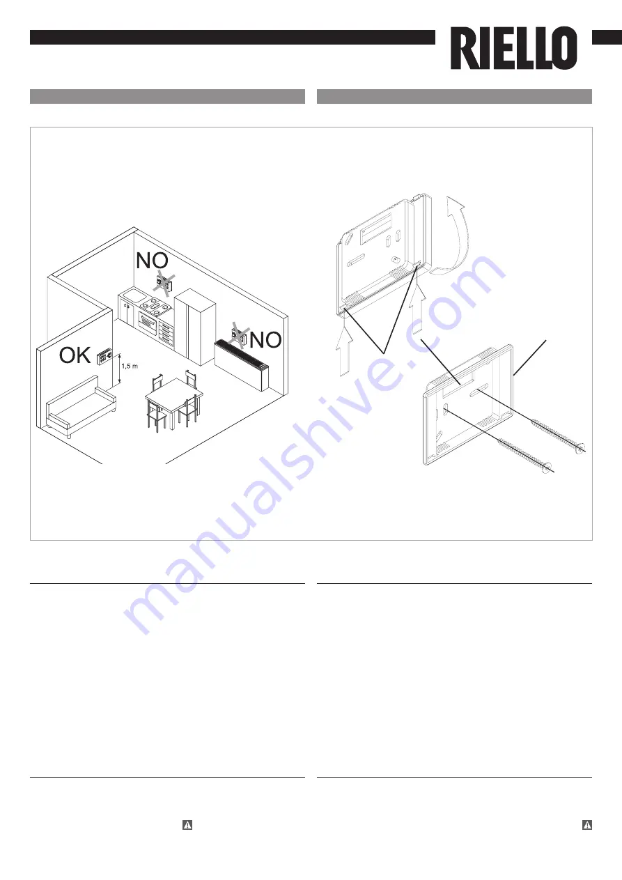
Page 1: ... adeguati eseguire le connessioni elettriche e richiudere il controllo facendo attenzione a non schiacciare i conduttori Montaggio e connessioni pannello di controllo remoto a muro EN Preliminary instructions This instruction booklet is an integral part of the manual of the device on which you install the kit In that manual please refer to the WARNINGS and the BASIC SAFETY RULES CPD 35 CONTROL PAN...

Page 2: ...legato all ingresso CP rif A tutte le utenze vengono spente Se il contatto è aperto l unità è attiva se il contatto è chiuso è disattivata e alla pressione di un tasto il simbolo lampeggia When the contact connected to the CP ref A input is closed all the users connected will be switched off If the contact is open the unit is active if the contact is closed the unit is deactivated an by pressing a...

Page 3: ...heda di remotizzazione rispettandone la polarità Alimentare il controllo remoto unicamente con la scheda alimentatore da 230 12 VDC in dotazione Connect the RS485 line of the wall mounted remote control to one or more up to a maximum of 30 units equipped with electronic remote control through a bipolar cable suitable for RS485 serial connection keeping it separate from power supply cables Chase ou...

Page 4: ...nello spento indicazione resistenza attiva Il pannello comandi è dotato di memoria per cui tutte le impostazioni non andranno perse né in caso di spegnimento né in caso di mancanza di tensione The control panel has its own memory therefore no settings will be lost in case of shut down or power outage EN Wall command panel Wall command panel The display also shows status and eventual alarms through...

Page 5: ...l apparecchio o di metterlo in condizione di attesa Silenzioso consente di limitare la velocità di ventilazione ad un valore massimo più contenuto Tasto Operazione Display Premere il tasto ON stand by Da spento ad acceso Selezionare uno dei 4 modi di funzionamento premendo il relativo tasto EN Wall command panel The various functions are set with the 8 backlit keys To manage the device through the...

Page 6: ...emperatura Tasto Operazione Display Impostare con l ausilio dei due tasti aumento e diminuzione il valore di temperatura desiderato in ambiente visualizzato sui 3 digit del display 20 5 EN Heating cooling operation mode setting Key Operation Display Keep Heating Cooling pressed down for about 2 seconds to switch the operation mode between heating and cooling shown through the 2 active heating or a...

Page 7: ...rmico ed acustico Funzionamento alla massima velocità di ventilazione Tasto Operazione Display Tener premuto il tasto Funzionamento Max L attivazione della funzione viene segnalata dall accensione del relativo simbolo a display EN Fan speed adjustment will occur automatically between a minimum and a maximum value according to the effective distance of the environment temperature from the set point...

Page 8: ... the display Use the key to bring the value to 00 and wait 20 seconds to check for the correct setting 00 0 Dopo un periodo di 20 secondi dall ultima azione l illuminazione del pannello viene appositamente ridotta per aumentare il comfort nelle ore notturne e sul display viene visualizzata la temperatura ambiente Se questa luminosità fosse ancora percepita come fastidiosa è possibile far spegnere ...

Page 9: ...i casi la misurazione diverga dalla temperatura reale Attraverso questa funzione è possibile regolare il valore misurato visualizzato a display in un range di 10 C a passi di 0 1 C Utilizzare tale regolazione con cautela e solo dopo aver riscontrato effettivamente scostamenti rispetto alla reale temperatura ambiente con uno strumento affidabile In same cases the detected values might not represent...

Page 10: ...erfezionamento di tutta la sua produzione le caratteristiche estetiche e dimensionali i dati tecnici gli equipaggiamenti e gli accessori possono essere soggetti a variazione As the manufacturer is constantly improving its products the aesthetic or dimensional features the technical data the equipment and accessories indicated could be subject to variations IT EN ...

Reviews: