background image

36

COMMISSIONING AND MAINtENANCE

Carefully check for absence of leakages from the closing 
point of the plug.

Do not force beyond the stop point to prevent damaging the 
shaft and causing leakage as a consequence.

Use equipment suitable for the system refrigerant.

Use only the system refrigerant.

Any gas leaks indoors can generate toxic gases if they come 
into contact with naked flames or high temperature bodies, 
in case of leaks, please air the rooms thoroughly.

Take anti-static precautions in case of weather conditions 
where humidity is less than 40%.

Avoid using mobile phones.

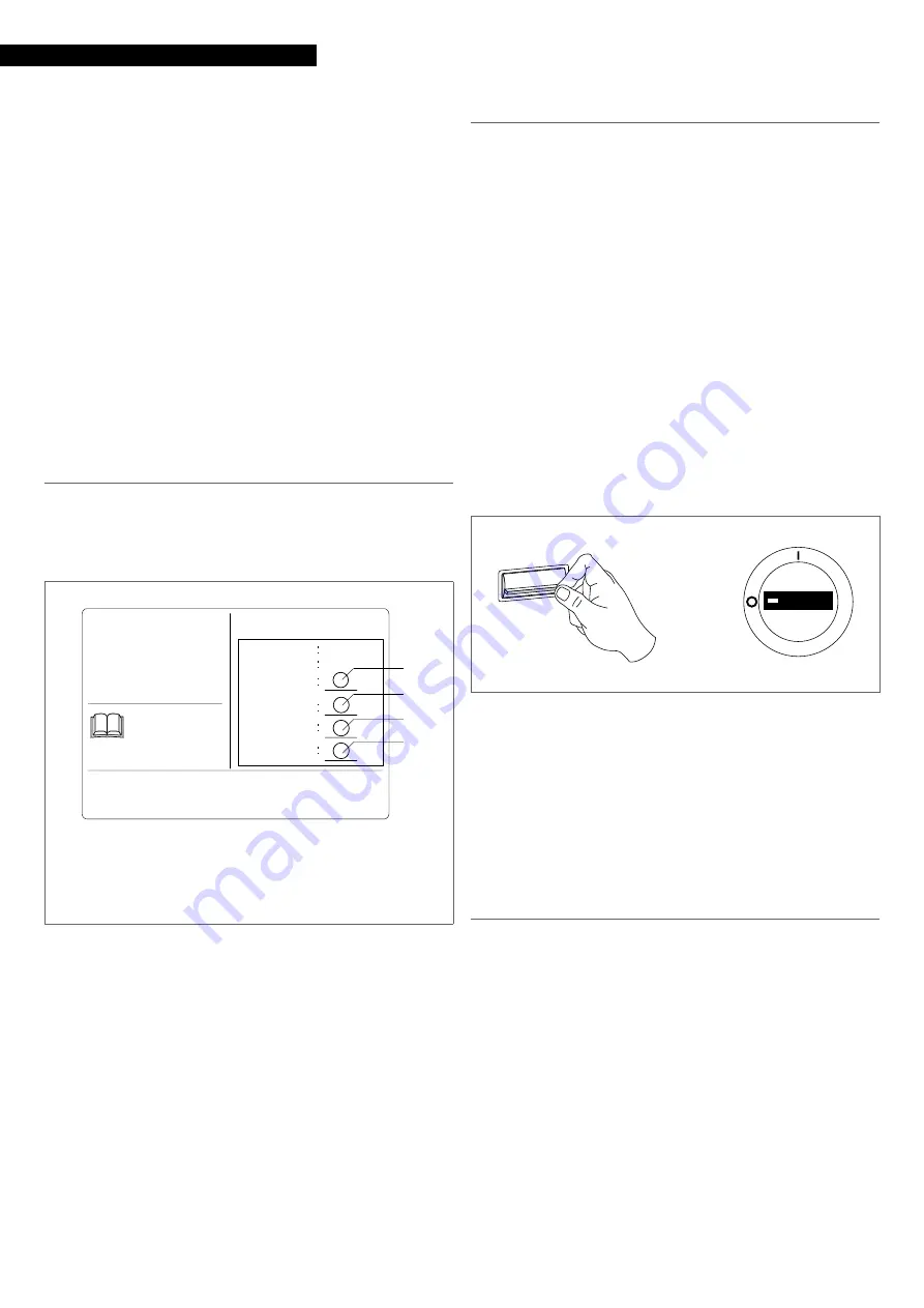
3.2.1

  Refrigerant label

In base alla Normativa CE n. 517/2014 su determinati gas floru-
rati ad effetto serra, è obbligatorio indicare la quantità totale 
di refrigerante presente sistema installato. Tale informazione è 
presente nella targhetta tecnica presente nell'unità esterna.

Standard charge

Additional charge

Total charge

Equivalent total weight of CO2

QUESTO APPARECCHIO CONTIENE 

GAS AD EFFETTO SERRA COPERTI 

DAL PROTOCOLLO DI KYOTO.   

INFORMAZIONI SUL REFRIGERANTE 


Refrigerante

Carica addizionale

Carica totale

Carica di fabbrica

(vedi etichetta tecnica)

É VIETATO DISPERDERE


IL GAS R32 DIRETTAMENTE


IN ATMOSFERA  

Istruzioni per compilare l’Etichetta “F-Gas Label”:

1 - Annotare le quantità sull’etichetta con inchiostro indelebile

2 - Collocare l’adesivo plastico di protezione (consegnato assieme al manuale)

3 - Peso equivalente CO2 del sistema in tonnellate = Carica totale in kg / 1000 x GWP

GW

P

675

R32

A

B

C
D

Peso equivalente CO2

kg
kg
kg

t

To write the tag:


note the quantity onto the label with indelible ink


place the refrigerant gas label on the outdoor unit

This unit contains fluorinated greenhouse gases covered 
by the Kyoto protocol. Maintenance and disposal activities 
must be carried out exclusively by skilled personnel.

Global warming potential of the R32 refrigerant gas: GWP=675

If necessary, the refrigerant must be recovered and not di-
spersed into the environment.


0

It is forbidden to disperse the refrigerant into the environ-
ment.


0

3.3

  Ordinary maintenance

Routine maintenance is fundamental for keeping the equip-
ment efficient, safe and reliable. It can be performed periodi-
cally by the Technical Support Service, whose staff is technically 
qualified and can use genuine spare parts, if necessary.

For units installed in a seaside environment, the mainte-
nance intervals shall be halved.

Original conditions must be restored after performing the 
required maintenance operations.

All described operations MUST be carried out under the fol-
lowing conditions:


cold device


device NOT supplied with electric power


suitable personal protection equipment


0

Do not open the access covers and carry out technical or 
cleaning activities before disconnecting the unit from the 
power grid by positioning the system's main switch in the 
"OFF" position.

ON 

OFF 


position the system's main switch in the "OFF" position.

Wait 10 minutes before touching the device electric compo-
nents.

Check with a tester that the voltage between the power 
supply connectors of the main electronic board is lower 
than 10 Vdc.

Yearly operations

The annual maintenance plan includes the following checks:


power supply voltage


electric connection tightening


status of cooling and hydraulic joint


finned coil cleaning


electric absorption


fan grille cleaning


Cleaning the heat exchanger fins

The thermal exchange bank must be cleaned with compressed 
air.
Cleaning must be carried out at least once a year, according to 
the location of the unit, as dirt accumulating between the fins 
narrows the passage section and reduces the exchange capa-
bility.


check the alignment of the bank's aluminium fins and, if 
necessary, straighten them with the appropriate comb

Summary of Contents for 20153499

Page 1: ...AARIA PRO P SERIES R32 cod Doc 0093005 rev 1 07 2020 EN INSTALLATION AND TECHNICAL SERVICE INSTRUCTIONS ...

Page 2: ...um comfort at length with a high degree of reliability efficiency quality and safety While your technical skills and knowledge will certainly be more than sufficient this booklet contains all the information that we have deemed necessary for the device s correct and easy installation Thank you again and keep up the good work RIELLO COMPLIANCE R AARIA PRO P heat pumps are compliant with the followi...

Page 3: ...connection p 32 3 COMMISSIONINGANDMAINTENANCE p 35 3 1 Preparation for first commissioning p 35 3 2 Putting into service p 35 3 3 Ordinary maintenance p 36 3 4 Operation signal and alarms p 37 4 DISPOSAL p 41 The following symbols are used on the product Avoid proximity to sources of ignition in continuous operation open flames gas household appliances electric stoves lit cigarettes etc For more i...

Page 4: ... Promptly con tact your local R Technical Support Service and do not perform any interventions upon the device on your own 9 The units contain refrigerant gas operate carefully so as to avoid damaging the gas circuit and the fin bank 9 Do not place any inflammable object spray cans within a 1 metre radius from the air expulsion 9 According to EU Regulation no 517 2014 regarding certain fluorinated...

Page 5: ...he compressor is excessive gas delivery temperature sensor which transmits the de tected value to the electronic board that is triggered in case of overtemperature 110 C anti freeze sensor which transmits the temperature value as detected by the heat exchanger to the electronic board that is triggered when the heat exchanger is clogged by frost formations suction temperature sensor which transmits...

Page 6: ...ODEL 1070 M 1 Terminal blocks cover 2 Four way valve 3 Filter 4 Heat exchanger 5 Electric fan 6 Refrigerant connections 7 Compressor 8 Intake separator 9 Connections cover 10 Upper panel 11 Fan protection grille 1 3 2 4 5 7 11 8 6 9 10 ...

Page 7: ...ation MODEL 1100 M 1 Terminal blocks cover 2 Four way valve 3 Filter 4 Heat exchanger 5 Electric fan 6 Refrigerant connections 7 Compressor 8 Intake separator 9 Upper panel 10 Fan protection grille 1 2 3 4 5 6 7 8 9 10 ...

Page 8: ... MODEL 1125 M 1125 T 1 Compressor 2 Intake separator 3 Intake separator 4 Four way valve 5 Heat exchanger 6 Electric fan 7 Refrigerant connections 8 Electrical box 9 Upper panel 10 Fan protection grille 1 10 6 2 4 3 5 7 8 9 ...

Page 9: ...EL 1140 T 1 Intake separator 2 Compressor 3 Intake separator 4 Muffler 5 Four way valve 6 Heat exchanger 7 Electric fan 8 Refrigerant connections 9 Electrical box 10 Upper panel 11 Fan protection grille 1 2 5 4 3 7 6 8 9 11 10 ...

Page 10: ... Capacity at rated air flow kW 8 00 Absorbed power at rated air flow kW 2 16 COP kW kW 3 71 Capacity at maximum air flow kW 8 50 Absorbed power at maximum air flow kW 2 90 Capacity at minimum air flow kW 0 70 Absorbed power at minimum air flow kW 2 40 Enery data for Average climatic profile 4 Pdesign at 10 C kW 5 60 SCOP kW kW 4 00 Energy class A Annual energy cons kWh annum 1959 Energy data for W...

Page 11: ...ow kW 8 00 10 20 12 30 14 30 Absorbed power at rated air flow kW 2 20 2 91 3 80 4 67 COP kW kW 3 71 3 50 3 08 3 06 Capacity at maximum air flow kW 8 20 10 50 13 00 15 00 Absorbed power at maximum air flow kW 3 00 4 00 5 60 7 20 Capacity at minimum air flow kW 0 30 3 00 1 80 3 00 Absorbed power at minimum air flow kW 0 10 0 50 0 30 1 00 Enery data for Average climatic profile 4 Pdesign at 10 C kW 5...

Page 12: ...8 00 10 20 12 20 14 50 12 20 15 00 Absorbed power at rated air flow kW 2 10 2 20 2 91 3 80 3 91 3 80 4 02 COP kW kW 3 71 3 71 3 50 3 25 3 71 3 40 3 73 Capacity at maximum air flow kW 8 00 8 20 10 50 13 50 16 00 13 50 17 00 Absorbed power at maximum air flow kW 3 00 3 00 4 00 5 60 7 20 5 60 7 20 Capacity at minimum air flow kW 0 30 0 30 3 00 2 90 3 50 2 90 3 50 Absorbed power at minimum air flow kW...

Page 13: ...w kW 7 50 10 20 12 50 14 10 Absorbed power at rated air flow kW 2 02 3 07 3 80 4 02 COP kW kW 3 71 3 32 3 25 3 51 Capacity at maximum air flow kW 8 50 10 50 13 50 16 00 Absorbed power at maximum air flow kW 3 00 4 00 5 60 7 20 Capacity at minimum air flow kW 2 00 3 00 2 90 3 50 Absorbed power at minimum air flow kW 0 50 0 50 0 30 1 00 Enery data for Average climatic profile 4 Pdesign at 10 C kW 5 ...

Page 14: ...z 15 15 20 20 20 Nominal current consumption A 9 10 12 70 16 00 5 70 6 80 Max current input A 13 00 17 40 26 00 9 50 11 00 Minimum current consumption A 0 30 0 50 1 50 2 40 1 00 Electrical characteristics Power supply V Ph Hz 220 240 1 50 60 380 415 3 50 60 Compressor Compressor Type Twin Rotary Rotary Oil Type FW68S Oil charge l 0 35 0 80 0 87 0 87 1 25 Refrigerant Type R32 Refrigerant charge kg ...

Page 15: ...ements 1 224 1 225 12 88 4 64 1 43 0 96 1 30 14 50 5 22 1 61 1 08 1 90 30 98 11 15 3 44 2 30 2 00 34 32 12 36 3 81 2 55 2 30 45 39 16 34 5 04 3 38 2 60 58 00 20 88 6 44 4 31 3 00 77 22 27 80 8 58 5 74 3 50 105 11 37 84 11 68 7 82 A Minimum floor area B Refrigerant charge C Floor D Window E Wall F Ceiling 110 A m 82 5 55 27 5 0 1 1 75 3 35 2 5 4 B kg C D E F ...

Page 16: ... air inside the rooms During the wintertime the heat pump extracts the thermal energy from the outdoor air and delivers it to the room air the reby heating it During the summertime the cycle is reversed and the thermal energy is extracted from the room air which is cooled and is delivered to the outdoor air A Outdoor unit B Indoor unit 1 Compressor 2 Discharge temperature sensor 3 Cycle reversal v...

Page 17: ... the packaging below the unit Document envelope Instruction s book for the installer and for the Technical Service in Italian Instruction s book for the installer and for the Technical Service in English Warranty Spare parts labels energy label etichetta gas refrigerante contact sheet It is also supplied as kit Condensate outlet hose 4 x vibration dampers 5 mm hex wrench 2 screws to connect refrig...

Page 18: ...the equipment in the installation place cut strapping bands lift and remove the cardboard pack handle the unit by grasping the handles provided remove the document envelope 9 In manual operation it is compulsory to respect always the maximum weight per person provided for by the national laws and standards 9 Handle with care 9 The equipment must always be handled vertically 9 Do not tilt the equip...

Page 19: ...stance from opposing winds direct exposure to sunlight and proximity to heat sources 9 Avoid placing the unit less than 1 metre away from radio and video systems 9 If the unit is installed in a windy location fit an anti wind grille to protect the fan and check the correct functioning of the unit 9 Decide where to place the unit considering the length of co oling lines and the maximum difference o...

Page 20: ...sitioned on a sufficiently rigid surface that will not transmit any vibrations to the underlying or adjacent ro oms 9 Use the anti vibration supports supplied with the device A B C D Model 1070 M 1100 M 1125 M 1125 T 1140 T Foot print dimensions Model 1070 M 1100 M 1125 M 1125 T 1140 T A mm B mm 633 660 660 660 660 C mm D mm 340 400 405 405 405 They can be placed on the floor or suspended on suppo...

Page 21: ... 9 While operating in heating mode the unit generates con densate which will deposit on the support surface if there is not discharge This could freeze if the outdoor temperatures are below zero thus creating a hazard In this case appro priate barriers should be installed in order to prevent people from approaching the unit 1 Lifting from the top 2 Condensate discharge connector 1 2 Model 1070 M 1...

Page 22: ...on 9 2 10 Refrigerating connection The dimensions and positions of R AARIA PRO P cooling con nections are shown hereunder MODEL 1070 1100 1 Liquid line connection 2 Gas line connection 3 Service connection 1 2 3 MODEL 1125 1140 1 Liquid line connection 2 Gas line connection 1 2 Model 1070 M 1100 M 1125 M 1125 T 1140 T Refrigerant connections Liquid line connection Inches 3 8 Gas line connection In...

Page 23: ...ith the risk of damages might ensue 9 Use copper pipes for cooling systems 9 Use connecting pipes and tools appropriate for the system s refrigerant 0 0 It is forbidden to use second hand cooling lines since their flare connection seal is not guaranteed 0 0 It is forbidden to use pre charged cooling lines 0 0 It is forbidden to carry out welding operations with refrige rant inside the cooling circ...

Page 24: ...al on the joints Pipe insulation Connection pipes must be thermally insulated to prevent di spersions of heat or formation of condensate 1 Gas pipe 2 Condensation discharge 3 Liquid pipe 4 Heat insulation 5 Adhesive tape 5 4 4 1 2 3 insulate the liquid and gas pipes separately use insulating material that is thicker than 15 mm ensure that the insulating material adheres to the pipe wi thout gaps f...

Page 25: ...checked The refrigerating circuit built on site needs to be checked inste ad To check tightness keep the outdoor unit shut off valves closed A High pressure B Low pressure 1 Pressure regulator 2 Nitrogen cylinder 3 Pressure gauge unit 4 3 way valve service connection N2 A B 1 2 3 4 1 3 way valve service connection 1 charge the circuit with nitrogen through the service con nection on the 3 way shut...

Page 26: ...inutes check that the pressure has not risen again If the pressure has risen again 1 2 way shut off valve 2 On off valve cover plug 3 Hex wrench A Opening by 1 4 of a turn A 3 1 2 open the 2 way shut off valve by a quarter of a turn close it after 6 seconds so as to allow a small quantity of refrigerant into the circuit detect the leak using a solution of water and soap fix the leak recreate the p...

Page 27: ...e plug 9 Do not force beyond the stop point to prevent damaging the shaft and causing leakage as a consequence 9 Once the check has been completed remove any residues of the water soap solution 9 Do not use the same vacuum pump with different refrige rants 9 The vacuum pump requires regular maintenance and the oil s clarity must also be checked 9 Afterhaving created thevacuum and established the e...

Page 28: ...C W B W R DC FAN MAIN CONTROL PCB DRIVE MOUDLE E E Y G W B Y G 1 N 2 L 3 C W BL U V W P N AC L LI AC N L0 CN25 N P CN28 N L CN11 4 WAY VALVE G G B CAP CN15 VALVE A LECTRIC XPANSION M VALVE MOTOR CAP CAP COMPRESSOR CN7 CN6 AC N OUT AC L OUT W B FUSE2 T3 15A 250VAC Q X CN47 SUCTION TEMPERATURE SENSOR DEFROST TEMPERATURE SENSOR COMPRESSOR TEMPERATURE SENSOR AMBIENT TEMPERATURE SENSOR TC CS HW CN17 FU...

Page 29: ...29 Installation MODEL 1100 M ...

Page 30: ...on in future 2 SW6 is used for central control adress selection refer to service manual to get more details 3 Once out of factory do not change the switches of SW1 SW6 SW7 SW8 without technical guidence 4 Can do the parameters checking work by button switches SW2 SW3 SW4 SW5 and digital display LED 3 refer to service manual to get more details 5 For maintenance safety please operate after pow er s...

Page 31: ...31 Installation MODEL 1125 T 1140 T ...

Page 32: ...n input 1 1 Electric connection input 1 ON OFF position the system s main switch in the OFF position 9 Wait 10 minutes before touching the device electric compo nents 9 Check with a tester that the voltage between the power supply connectors of the main electronic board is lower than 10 Vdc To access the terminal board MODEL 1070 1100 1 Terminal blocks 2 Terminal board cover panel 1 2 MODEL 1125 1...

Page 33: ...it 2 Power supply connection terminal board 3 Wire retainer 4 Earth screw 1 3 2 4 remove the wire retainer make electrical connections according to the diagrams be low MODEL 1070 M 1100 M 1125 M A Outdoor unit B Indoor unit C System main switch 1 N 2 L 3 C A B L N 230V 1 N 50HZ C 1 N 2 L 3 C 1 N 2 L MODEL 1125 T 1140 T A Outdoor unit B Indoor unit C System main switch 1 N 2 L 3 C A B S T N R 400V ...

Page 34: ...the power network disconnect devices must be equipped with contact openings 3 mm in order to allow for complete disconnection in accordance with the con ditions required Mandatory items have an omnipolar magneto thermal circuit breaker and a padlockable disconnecting switch compliant with the IEC EN Standards contact opening of at least 3 mm with adequate breaking power and differential protection...

Page 35: ...e first commissioning After starting the device check that the current consumed by the compressor is less than the maximum permitted the device is operating under the recommended operating conditions the unit is able to stop and start up again 9 Should any of the above listed controls have problems turn the device off and call the Technical Service immediately 9 Do not touch the device pipes to pr...

Page 36: ... be carried out exclusively by skilled personnel 9 GlobalwarmingpotentialoftheR32refrigerantgas GWP 675 9 If necessary the refrigerant must be recovered and not di spersed into the environment 0 0 It is forbidden to disperse the refrigerant into the environ ment 0 0 3 3 Ordinary maintenance Routine maintenance is fundamental for keeping the equip ment efficient safe and reliable It can be performe...

Page 37: ...filters 1 Upper panel 2 Electric panel cover 1 2 unscrew the fastening screws remove the top panel unscrew the fastening screws remove the electric panel cover Faults are signalled by means of LED 1 blinking Led 1 Description Remarks 1 External unit microprocessor fault The unit resets after problem resolution 2 Power module fault After 3 consecutive interventions in 10 minutes the unit resets aft...

Page 38: ... an accurate check of the device components is required Contact R Technical Support Service 9 Indoor units with display signal faults with an alphanumeric code Consult the matching outdoor unit instruction booklet for the installer 9 Model 1100 1125 1140 Faults are indicated by a flashing code displayed on the display located on electronic circuit board 1 Display 1 utdoor unit display Malfunction ...

Page 39: ...d temperature too low The indoor unit exchanger probe detects a temperature too low The outdoor unit stops to prevent frost of the heat exchanger and too cold air emission 22 Overcurrent to the power factor correction circuit PFC Overcurrent detected to the power factor correction circuit PFC Not restorable 23 Compressor control module PIM temperature too high The compressor control module probe d...

Page 40: ...10 minutes before restarting the unit 9 To restore operating conditions cut and restore the power supply 9 If the fault occurs again an accurate check of the device components is required Contact R Technical Support Service 9 Indoor units with display signal faults with an alphanumeric code Consult the matching outdoor unit instruction booklet for the installer ...

Page 41: ...erials shall be disposed of separately so as to re cover and recycle them Refrigerant and oil must be recovered and not dispersed into the environment At the end of its service life the device shall be disposed of according to the existing le gislation ...

Page 42: ......

Page 43: ......

Page 44: ...l 39 0442 630111 fax 39 0442 630371 www riello it As the manufacturer is constantly improving its products the aesthetic or dimensional features the technical data the equipment and accessories indicated could be subject to variations ...

Reviews: