background image

2903266

16 

GB

Electrical system

7.1

Notes on safety for the electrical wiring

Before carrying out any maintenance, cleaning or checking oper-
ations:

If the cover is still present, remove it and proceed with the electri-
cal wiring according to the wiring diagrams.
Use flexible cables in compliance with the EN 60 335-1 standard.
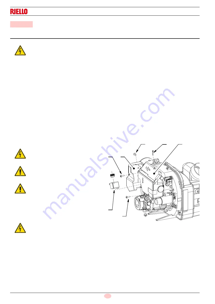
7.1.1

Control box

To remove the control box (Fig. 13) from the burner follow of the
istruction: 

Loosen the screw 1) and remove protection 6) of the electri-
cal connections and coil.

Loosen the screws 2), open the protection 3) and remove all
components.

Remove the coil 4) and loosen the two screws 5).

Move a little the control box and remove the high voltage
leads.

 7

Electrical system

DANGER

The electrical wiring must be carried out with the electrical supply disconnected.

Electrical wiring must be carried out by qualified personnel and in compliance with the regulations currently in
force in the country of destination. Refer to the wiring diagrams.

The manufacturer declines all responsibility for modifications or connections different from those shown in the wir-
ing diagrams.

Do not invert the neutral with the phase in the electrical supply line. 

Check that the electrical supply of the burner corresponds to that shown on the identification label and in this man-
ual.

The burners have been set for intermittent operation. This means they should compulsorily be stopped at least
once every 24 hours to enable the control box to perform checks of its own start-up efficiency. Normally the
boiler's thermostat/pressure switch ensures the stopping of the burner.
If this is not the case, it is necessary to apply in series with L-N a timer switch that turns off the burner at least
once every twenty-four hours. Refer to the wiring diagrams.

The electrical safety of the device is obtained only when it is correctly connected to an efficient earthing system,
made according to current standards. It is necessary to check this fundamental safety requirement. In the event of
doubt, have the electrical system checked by qualified personnel.

The electrical system must be suitable for the maximum input power of the device, as indicated in the manual,
checking in particular that the section of the cables is suitable for the input power of the device.

For the main power supply of the device from the electricity mains:

- do not use adapters, multiple sockets or extensions;
- use an omnipolar switch, as indicated by the current safety standards.

Do not touch the device with wet or damp body parts and/or in bare feet.

Do not pull the electric cables.

DANGER

Disconnect the electrical supply from the burner
by means of the main system switch.

DANGER

Turn off the fuel interception tap.

DANGER

Avoid condensate, ice and water leaks from form-
ing.

DANGER

This operation must be performed with the burner
turned off and mains power disconnected.

D7358

5

5

4

1

3

2

6

Fig. 13

Summary of Contents for 20015255

Page 1: ...se and maintenance instructions Kerosene burners One stage operation CODE MODEL TYPE 3516010 RDB1 WORCESTER GREENSTAR 12 18 484LD2X 3516020 RDB2 2 WORCESTER GREENSTAR 18 25 744LD2SX 20015255 RDB2 2 WO...

Page 2: ...Original instructions...

Page 3: ...4 4 Burner dimensions 9 4 5 Firing rates 9 5 Installation 10 5 1 Notes on safety for the installation 10 5 2 Handling 10 5 3 Preliminary checks 10 5 4 Installer Servicer notes for the use of Gas oil w...

Page 4: ...23 8 8 11 Reset push button anomaly 23 8 8 12 External lockout indicator 24 8 8 13 Frequency main supply anomaly 24 8 8 14 Internal voltage anomaly 24 8 8 15 Checking the fan motor 24 8 8 16 Checking...

Page 5: ...th the following Technical Standards EN 12100 EN 267 According to the European Directives MD 2006 42 EC Machine Directive LVD 2014 35 EU Low Voltage Directive EMC 2014 30 EU Electromagnetic Compatibil...

Page 6: ...ied out correctly may cause damage to the ma chine and or injury to people DANGER DANGER LIVE COMPONENTS This symbol indicates operations which if not car ried out correctly lead to electric shocks wi...

Page 7: ...ance and care of those burner components most likely to be subject to wear and tear the use of non original components including spare parts kits accessories and optional force majeure The manufacture...

Page 8: ...quality bio compatible oil filter at the tank and then a second ary filter of 60 Microns protecting the burner from contamina tion If an existing oil storage tank is to be used then in addition to the...

Page 9: ...d maintenance errors or to improper use 3 3 Basic safety rules Children or inexpert persons must not use the appliance Under no circumstances must the intake grids dissipation grids and ventilation ve...

Page 10: ...el Kerosene viscosity 1 6 6 mm2 s at 20 C Hi 11 97 kWh kg Electrical supply Single phase 50Hz 230V 10 Motor Run current 0 7A 2700 rpm 283 rad s Capacitor 4 5 F Ignition transformer Secondary 18 kV 25...

Page 11: ...line from the desired delivery and a horizontal line from the pressure in the combustion chamber The intersection of these two lines is the work point which must lie within the firing rates Fig 2 204...

Page 12: ...s for the burner can be highly dangerous if not carried out with the great est attention keep any unauthorised people at a distance check the integrity and suitableness of the available means of handl...

Page 13: ...at the tank and a secondary 60 micron filter are used to protect the burner pump and nozzle from con tamination The burner hydraulic components and flexible oil lines must be suitable for bio fuel use...

Page 14: ...ll be met if you use flues for pressure exhaust of flue gases the condensation kind Make sure the air intake tube s inlet is positioned so that it is not likely to be obstructed by foreign matter and...

Page 15: ...line 3 By pass screw 4 Gauge connection 5 Pressure adjuster 6 Vacuum gauge connection 7 Valve 8 Auxiliary pressure test point 2 1 3 4 5 6 7 8 D10934 Fig 9 WARNING Where gas oil containing bio diesel i...

Page 16: ...ength of the suction line I D internal diameter of the oil pipes NOTE The Tab B and Tab C show the maximum approximate lengths for the supply line depending on the difference in level length and the d...

Page 17: ...L max length of the suction line I D internal diameter of the oil pipes NOTE The Tab D shows the maximum approximate lengths for the sup ply line depending on the difference in level length and the d...

Page 18: ...operation This means they should compulsorily be stopped at least once every 24 hours to enable the control box to perform checks of its own start up efficiency Normally the boiler s thermostat press...

Page 19: ...ables and thermostat as well 7 1 2 Motor capacitor The proper positioning of motor capacitor cover is shown in the detail of Fig 15 To remove the motor capacitor cover from the burner loosen the screw...

Page 20: ...Hz 230V Main switch White WARNING Do not invert the neutral with the phase in the electrical supply line Check that the electrical supply of the burner corresponds to that shown on the identifica tion...

Page 21: ...urner WARNING The first start up of the burner must be carried out by qualified personnel as indicated in this manual and in compliance with the standards and regula tions of the laws in force WARNING...

Page 22: ...her of two positions To set the positions of the damper proceed as follows remove the secondary air damper B Fig 19 loosing the screws 1 Loosen the screw 2 and rotate the main air damper A to the requ...

Page 23: ...tion time Only 3 consecutive re ignition attempts are permitted Fig 21 Loss of flame during operation R ecycle max 3 attempts t1 t3 t4i ts t5i t4l HT FM ID V1 F LED F LED P M t3i POW ERSUPPLY Signal n...

Page 24: ...eset 0 8 tr Re cycles Max no 3 repetitions of complete start up sequence if there is a flame failure during operation the final action at the last attempt following flame failure is a lock out 3 re cy...

Page 25: ...hen a new heat request oc curs power supply is applied to the burner all possible attempts at re ignition are reset maximum 3 8 8 8 Presence of an extraneous light or parasite flame If when the fan mo...

Page 26: ...burner restarts 8 8 15 Checking the fan motor The control box automatically detects the presence of the fan mo tor and in the event of a fault it performs a lockout The lockout is indicated by the bl...

Page 27: ...number of times programmed 0 5 sec ON 0 5 sec OFF 8 10 3 Intermittent operation Sequence for enable disable Programming allowed in OPERATION Press the button for 20 sec t 25 sec GREEN led flashing 3...

Page 28: ...heat demand Pre heating not terminated if there is a heater After 600 seconds fault in the resistor of the oil pre heater fault in the switch or start up thermostat the short circuit socket is not co...

Page 29: ...to either the suction line or the pump If the problem lies in the suction line check to make sure that the filter is clean and that air is not entering the piping Hoses Check periodically the flexibl...

Page 30: ...ts Allow the burner to work for 10 min and then check the combustion readings with the parameters indicated within the appliance instruction manual Then carry out a combustion check verifying Smoke te...

Page 31: ...are wrongly inserted OFF Check and connect all the plugs and sockets prop erly The heater is faulty or the P short cir cuit socket is not connected if there is not a heater Replace them The burner go...

Page 32: ...Subject to modifications RIELLO S p A I 37045 Legnago VR Tel 39 0442 630111 http www riello it http www riello com...

Reviews: