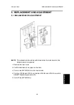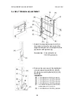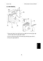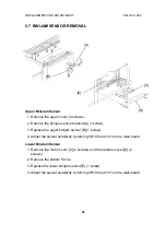
5.2 STAPLE POSITION ADJUSTMENT
NOTE:
This adjustment should be performed when the main board or staple
unit is replaced.
X Direction
1. Check the position of the staple [A] on the copy paper.
2. Remove the upper cover [B] (4 screws),open the vertical transport door
[C] and remove the left front cover [D] (4 screws).
3. Lower the staple unit [E] by manually turning the timing belt [F] of the
staple unit positioning motor in the direction of the arrow.
4. Remove the staple unit upper cover [G] (1 screw).
5. Loosen the two screws [H] and adjust the staple unit position.
6. Retighten the screws [H].
Y Direction
1. Check the position of the staple [A] on the copy paper.
2. Remove the rear cover.
3. Adjust the staple position by setting the DIP SW101.
Y
X
[A]
[C]
[B]
[D]
[F]
[G]
[H]
[E]
REPLACEMENT AND ADJUSTMENT
6 March 1992
38
Summary of Contents for ST23
Page 1: ...RICOH ST23 SERVICE MANUAL ...


