DIP SWITCH SETTINGS 16 February 2000
4-4
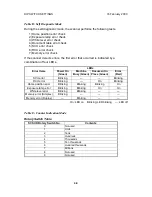
Table D: Self Diagnostic Mode
During the self-diagnostic mode, the scanner performs the following tests.
1) Home position error check
2) Exposure lamp error check
3) White level error check
4) Document table error check
5) SCU error check
6) RCU error check
7) Memory error check
If the scanner detects errors, the first error that occurred is indicated by a
combination of four LEDs.
LEDs
Error Items Power On
(Green)
Machine
Busy (Green)
Document in
Place (Green)
Error
(Red)
SCU error Blinking — — Blinking
RCU error Blinking — On Blinking
Home position error Blinking Blinking Blinking On
Exposure lamp error Blinking Blinking On On
White level error Blinking Blinking — —
Memory error (Simplex) Blinking — — —
Memory error (Duplex) — Blinking — —
On: LED on Blinking: LED blinking —: LED off
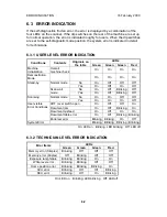
Table E: Counter Indication Mode
Rotary Switch Table
SCSI ID Rotary Switch No. Contents
0 Not used
1
Units
2 Tens
3 Hundreds
4 Thousands
5 Ten thousands
6 Hundred thousands
7 Millions
8 Not used
9 Not used


