COMPONENT LAYOUT
16 February 2000
1-4
1.2.2 REAR VIEW
No.
Name
Function
7
Reset switch
If this is pressed, the machine is reset.
8
DIP switches
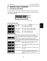
Used to select various scanning modes and test
modes.
9
Interface for reverse side
scanning
(Duplex model only)
Interface for the video signal during reverse side
scanning.
10
Video connector
For connecting the video cable
11
SCSI ID rotary switch
Used to select the SCSI ID and to select diagnostic
tests. Note that positions 8 and 9 are interpreted as
SCSI ID 7.
12
Power plug inlet
For connecting the power cord.
13
ADF cover
Open this cover to clear paper jammed at the input
side.
14
SCSI connectors cover
and SCSI connectors
(For connecting the SCSI cables.)
G413V501.WMF
13
10
11
12
7
8
9
14


