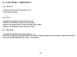
5-3 ELECTRONIC COMPONENTS
5-3-1 Modem
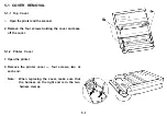
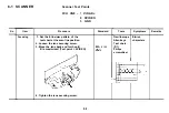
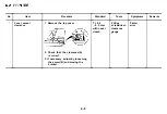
1. Remove the top cover (see section 5-1-1).
2. Take out the modem.
5-3-2 P S U
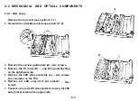
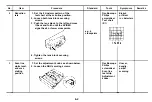
1. Remove the scanner unit (see section 5-2-2).
2. Remove the NIF (three screws, two connectors).
3. Remove the bracket that is on top of the PSU (four screws)
4. Remove the PSU (two screws, two connectors).
5-3-3 OP-PORT
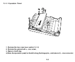
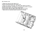
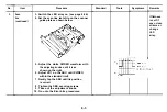
1. Remove the operation panel (see section 5- 1 -3).
2. Remove the upper scanner guide plate (four screws), feeding the ground wire through the opening in the plate.
3. Remove the OP-PORT PCB (12 screws, 3 connectors).
5-7
Summary of Contents for FAX07
Page 4: ...SECTION 1 ...
Page 8: ...SECTION 2 ...
Page 12: ...SECTION 3 ...
Page 13: ...3 1 EXTERNAL Guide to Components 3 1 ...
Page 14: ...3 2 INTERNAL Optical and Mechanical Components 3 2 ...
Page 16: ... Electronic Components 3 4 ...
Page 19: ...SECTION 4 ...
Page 52: ...Paper Leading Edge 4 3 3 ...
Page 54: ...SECTION 5 REMOVAL AND REPLACEMENT ...
Page 67: ...SECTION 6 ...
Page 74: ...SECTION 7 ...
Page 77: ...SECTION 8 T R O U B LE S H O O T I N G ...
Page 95: ......
Page 96: ......
Page 97: ......
Page 98: ......
Page 99: ......
Page 100: ......
Page 101: ......
Page 102: ......
Page 103: ......
Page 104: ......
Page 105: ......
Page 106: ...A H ...
Page 142: ... BIT SW 1C BIT No o 1 2 3 4 5 6 7 Function Remarks Not used Not used A 36 ...
Page 145: ...APPENDIX C POINT TO POINT DIAGRAM I C 1 ...
Page 146: ...APPENDIX D BLOCK DIAGRAMS 1 System Control D 1 ...
Page 147: ...2 Video Data Path Transmission D 2 ...
Page 148: ... Reception D 3 ...
Page 149: ... Copying D 4 ...
Page 150: ... Video Processing Circuit D 5 ...
Page 151: ...3 Communication Control D 6 ...
Page 152: ...4 Power Supply Distribution D 7 ...
Page 153: ... PSU D 8 ...
Page 154: ...APPENDIX E PCB LAYOUTS FCU 1 4 Parts Layout E 1 ...
Page 155: ...FCU 2 4 Parts Side E 2 ...
Page 156: ...FCU 3 4 Comp Side E 3 ...
Page 157: ...FCU 4 4 Reverse E 4 ...
Page 158: ...NIF 1 4 Parts Layout ...
Page 159: ...NIF 2 4 Parts Side E 6 ...
Page 160: ...NIF 3 4 Comp Side E 7 ...
Page 161: ...NIF 4 4 Reverse E 8 ...
Page 162: ...PSU 1 2 E 9 ...
Page 163: ...PSU 2 2 Reverse E 10 ...
Page 164: ...SBU 1 4 Parts Layout E 11 ...
Page 165: ...SBU 2 4 Parts Side E 12 ...
Page 166: ...SBU 3 4 ...
Page 167: ...SBU 4 4 Reverse E 14 ...

