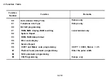


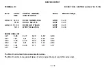

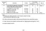
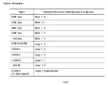
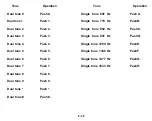


Parameter
No.
12
13
14
15
16
Description
Time until the next dial pulse is transmitted
(pause between dials, the time until DI relay
is opened after DS relay is opened). (T4)
Time waited when a pause is input.
DTMF tone on time (D0)
DTMF tone off time (D1)
DTMF tone transmission level
Notes:
1.
2.
3.
4.
Formula
N x 20 (ms)
N x 20 (ms)
N x 1 (ms)
N x 1 (ms)
– (15–N)
Factory Setting
UK, Universal
30
33
100
100
09
Asia
36
101
100
110
09
The above pulse dialing times (T0, T1, T2, T3) are the values for 10 pps.
Times for 20 pps are half those for 10 pps.
DS relay control should be done for the Europe type NCU which has a ground start selection.
The first ring may not be detected until Parameter 05 + Ringing Signal wavelength X (1 to 2.5).
N must be between 0 and 15.
Remarks
Notes 1, 2
Note 4
4-23
Summary of Contents for FAX07
Page 4: ...SECTION 1 ...
Page 8: ...SECTION 2 ...
Page 12: ...SECTION 3 ...
Page 13: ...3 1 EXTERNAL Guide to Components 3 1 ...
Page 14: ...3 2 INTERNAL Optical and Mechanical Components 3 2 ...
Page 16: ... Electronic Components 3 4 ...
Page 19: ...SECTION 4 ...
Page 52: ...Paper Leading Edge 4 3 3 ...
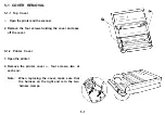
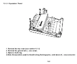
Page 54: ...SECTION 5 REMOVAL AND REPLACEMENT ...
Page 67: ...SECTION 6 ...
Page 74: ...SECTION 7 ...
Page 77: ...SECTION 8 T R O U B LE S H O O T I N G ...
Page 95: ......
Page 96: ......
Page 97: ......
Page 98: ......
Page 99: ......
Page 100: ......
Page 101: ......
Page 102: ......
Page 103: ......
Page 104: ......
Page 105: ......
Page 106: ...A H ...
Page 142: ... BIT SW 1C BIT No o 1 2 3 4 5 6 7 Function Remarks Not used Not used A 36 ...
Page 145: ...APPENDIX C POINT TO POINT DIAGRAM I C 1 ...
Page 146: ...APPENDIX D BLOCK DIAGRAMS 1 System Control D 1 ...
Page 147: ...2 Video Data Path Transmission D 2 ...
Page 148: ... Reception D 3 ...
Page 149: ... Copying D 4 ...
Page 150: ... Video Processing Circuit D 5 ...
Page 151: ...3 Communication Control D 6 ...
Page 152: ...4 Power Supply Distribution D 7 ...
Page 153: ... PSU D 8 ...
Page 154: ...APPENDIX E PCB LAYOUTS FCU 1 4 Parts Layout E 1 ...
Page 155: ...FCU 2 4 Parts Side E 2 ...
Page 156: ...FCU 3 4 Comp Side E 3 ...
Page 157: ...FCU 4 4 Reverse E 4 ...
Page 158: ...NIF 1 4 Parts Layout ...
Page 159: ...NIF 2 4 Parts Side E 6 ...
Page 160: ...NIF 3 4 Comp Side E 7 ...
Page 161: ...NIF 4 4 Reverse E 8 ...
Page 162: ...PSU 1 2 E 9 ...
Page 163: ...PSU 2 2 Reverse E 10 ...
Page 164: ...SBU 1 4 Parts Layout E 11 ...
Page 165: ...SBU 2 4 Parts Side E 12 ...
Page 166: ...SBU 3 4 ...
Page 167: ...SBU 4 4 Reverse E 14 ...


