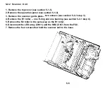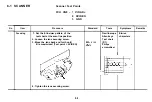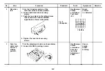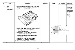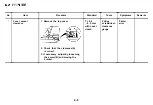
5-2-2 Scanner Unit
1. Remove the top cover (see section 5-1-1).
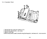
2. Remove the operation panel (see section 5-1-3).
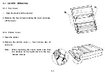
3. Remove the scanner guide plate– two screws (see section 5-2-1 step 3).
4. Remove the R1 roller – one E-ring and one bushing (see section 5-2-1 step 4).
5. Remove the R2 roller in the same way as the R1 roller.
6. Disconnect the LED array (CN11) and the SBU (CN7) from the FCU.
7. Remove the four screws that hold the scanner unit to the base.
5-5
Summary of Contents for FAX07
Page 4: ...SECTION 1 ...
Page 8: ...SECTION 2 ...
Page 12: ...SECTION 3 ...
Page 13: ...3 1 EXTERNAL Guide to Components 3 1 ...
Page 14: ...3 2 INTERNAL Optical and Mechanical Components 3 2 ...
Page 16: ... Electronic Components 3 4 ...
Page 19: ...SECTION 4 ...
Page 52: ...Paper Leading Edge 4 3 3 ...
Page 54: ...SECTION 5 REMOVAL AND REPLACEMENT ...
Page 67: ...SECTION 6 ...
Page 74: ...SECTION 7 ...
Page 77: ...SECTION 8 T R O U B LE S H O O T I N G ...
Page 95: ......
Page 96: ......
Page 97: ......
Page 98: ......
Page 99: ......
Page 100: ......
Page 101: ......
Page 102: ......
Page 103: ......
Page 104: ......
Page 105: ......
Page 106: ...A H ...
Page 142: ... BIT SW 1C BIT No o 1 2 3 4 5 6 7 Function Remarks Not used Not used A 36 ...
Page 145: ...APPENDIX C POINT TO POINT DIAGRAM I C 1 ...
Page 146: ...APPENDIX D BLOCK DIAGRAMS 1 System Control D 1 ...
Page 147: ...2 Video Data Path Transmission D 2 ...
Page 148: ... Reception D 3 ...
Page 149: ... Copying D 4 ...
Page 150: ... Video Processing Circuit D 5 ...
Page 151: ...3 Communication Control D 6 ...
Page 152: ...4 Power Supply Distribution D 7 ...
Page 153: ... PSU D 8 ...
Page 154: ...APPENDIX E PCB LAYOUTS FCU 1 4 Parts Layout E 1 ...
Page 155: ...FCU 2 4 Parts Side E 2 ...
Page 156: ...FCU 3 4 Comp Side E 3 ...
Page 157: ...FCU 4 4 Reverse E 4 ...
Page 158: ...NIF 1 4 Parts Layout ...
Page 159: ...NIF 2 4 Parts Side E 6 ...
Page 160: ...NIF 3 4 Comp Side E 7 ...
Page 161: ...NIF 4 4 Reverse E 8 ...
Page 162: ...PSU 1 2 E 9 ...
Page 163: ...PSU 2 2 Reverse E 10 ...
Page 164: ...SBU 1 4 Parts Layout E 11 ...
Page 165: ...SBU 2 4 Parts Side E 12 ...
Page 166: ...SBU 3 4 ...
Page 167: ...SBU 4 4 Reverse E 14 ...

