General Cautions
SM 4-1
D096
R
ep
la
cem
en
t
and
Adjus
tm
ent
4. REPLACEMENT AND ADJUSTMENT
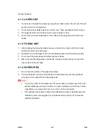
4.1 GENERAL CAUTIONS
Do not turn off the main switch while any of the electrical components are active. Doing so
may result in damage to units (such as the PCU) as they are pulled out or replaced.
4.1.1 PCU (PHOTOCONDUCTOR UNIT)
The PCU consists of the OPC drum, charge roller, development unit, and cleaning
components. Observe the following precautions when handling the PCU.
1. Never touch the drum surface with bare hands. If the drum surface is dirty or if you
have accidentally touched it, wipe it with a dry cloth, or clean it with wet cotton and then
wipe it dry with a cloth.
2. Never use alcohol to clean the drum. Alcohol will dissolve the drum surface.
3. Store the PCU in a cool dry place.
4. Do not expose the drum to corrosive gases (ammonia, etc.).
5. Do not shake a used PCU, as this may cause toner and developer to spill out.
6. Dispose of used PCU components in accordance with local regulations.
4.1.2 TRANSFER ROLLER
1. Never touch the surface of the transfer roller with bare hands.
2. Be careful not to scratch the transfer roller, as the surface is easily damaged.
4.1.3 SCANNER UNIT
1. Use alcohol or glass cleaner to clean the exposure and scanning glass. This will
reduce the static charge on the glass.
2. Use a blower brush or a water-moistened cotton pad to clean the mirrors and lenses.
3. Make sure to not bend or crease the exposure lamp’s ribbon cable.
4. Do not disassemble the lens unit. This will cause the lens and copy image to get out of
focus.
5. Do not turn any of the CCD positioning screws. This will put the CCD out of position.
Summary of Contents for D096
Page 1: ...D096 SERVICE MANUAL 005627MIU ...
Page 2: ......
Page 3: ...D096 SERVICE MANUAL ...
Page 4: ......
Page 5: ...D096 SERVICE MANUAL 005627MIU ...
Page 6: ......
Page 8: ......
Page 10: ......
Page 12: ......
Page 18: ......
Page 20: ......
Page 24: ......
Page 25: ...PRODUCT INFORMATION REVISION HISTORY Page Date Added Updated New None ...
Page 26: ......
Page 30: ...Overview D096 1 4 SM 1 4 OVERVIEW 1 4 1 COMPONENT LAYOUT ...
Page 34: ......
Page 35: ...INSTALLATION REVISION HISTORY Page Date Added Updated New None ...
Page 36: ......
Page 55: ...PREVENTIVE MAINTENANCE REVISION HISTORY Page Date Added Updated New None ...
Page 56: ......
Page 60: ......
Page 61: ...REPLACEMENT AND ADJUSTMENT REVISION HISTORY Page Date Added Updated New None ...
Page 62: ......
Page 110: ...Fusing D096 4 48 SM 4 9 6 THERMOSTAT 1 Hot roller See above 2 Thermostat A x 2 for each ...
Page 127: ...SERVICE TABLES REVISION HISTORY Page Date Added Updated New None ...
Page 128: ......
Page 153: ...TROUBLESHOOTING REVISION HISTORY Page Date Added Updated New None ...
Page 154: ......
Page 161: ...ENERGY SAVING REVISION HISTORY Page Date Added Updated New None ...
Page 162: ......
Page 167: ...D096 SERVICE MANUAL APPENDICES ...
Page 168: ......
Page 170: ......
Page 171: ...APPENDIX SPECIFICATIONS REVISION HISTORY Page Date Added Updated New None ...
Page 172: ......
Page 186: ......
Page 187: ...APPENDIX PREVENTIVE MAINTENANCE REVISION HISTORY Page Date Added Updated New None ...
Page 188: ......
Page 193: ...APPENDIX TROUBLESHOOTING GUIDE REVISION HISTORY Page Date Added Updated New None ...
Page 194: ......
Page 207: ...APPENDIX SP MODE TABLES REVISION HISTORY Page Date Added Updated New None ...
Page 208: ......
Page 244: ......
Page 246: ......

