Ricoh Aficio SP C231 Service Manual Download Page 73

DRUM

2-33

SM

C231

Det

a

iled

Sect

io

n

De

s

c

ri

ptions

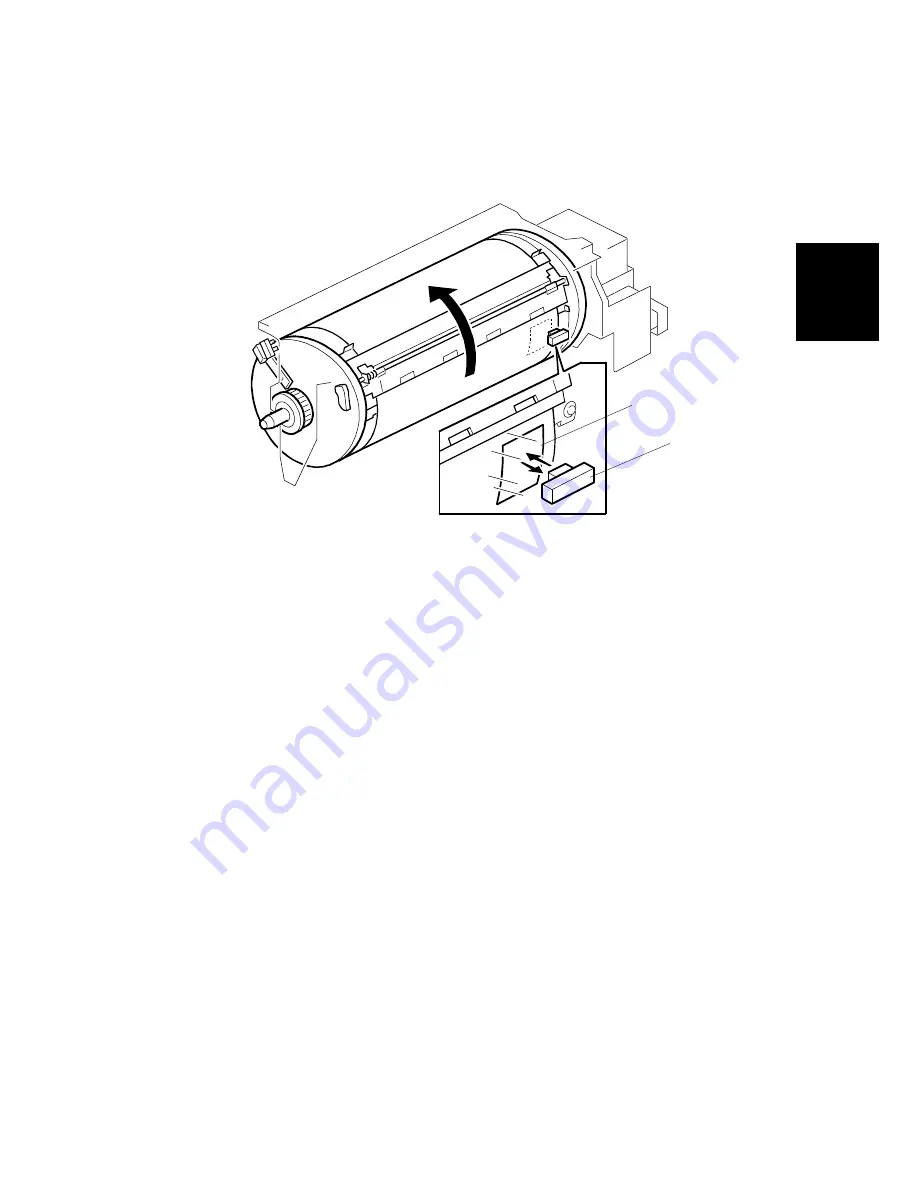
2.5.6  DETECTION OF MASTERS ON THE DRUM

The drum master sensor [B] detects whether a master is on the drum.

When there is a master on the drum, the black patch [A] is covered and the sensor
detects the light reflected from the master. Printing starts when the start key is
pressed. (If a new original is set, the master ejecting cycle is performed before
making a new master.)

When there is no master on the drum, the black patch [A] is exposed. The black
patch does not reflect light back to the sensor. Because of this, the master eject
process is skipped when a new master is made.

C231D571.WMF

[A]

[B]

Summary of Contents for Aficio SP C231

Page 1: ...SERVICE MANUAL PN RCSMC231 C231 RICOH GROUP COMPANIES...

Page 2: ......

Page 3: ...SERVICE MANUAL C231 RICOH GROUP COMPANIES...

Page 4: ......

Page 5: ...C231 SERVICE MANUAL PN RCSMC231...

Page 6: ......

Page 7: ...tion Users of this manual should be either service trained or certified by successfully completing a Ricoh Technical Training Program Untrained and uncertified users utilizing information contained in...

Page 8: ......

Page 9: ...LEGEND PRODUCT CODE COMPANY RICOH SAVIN GESTETNER C231 JP1030 3150DNP 5306L DOCUMENTATION HISTORY REV NO DATE COMMENTS 7 98 Original Printing...

Page 10: ......

Page 11: ...rs 1 14 Solenoids 1 15 Switches 1 15 Sensors 1 15 Counters 1 16 Others 1 16 1 6 DRIVE LAYOUT 1 17 DETAILED SECTION DESCRIPTIONS 2 1 2 1 SCANNER AND OPTICS 2 1 2 1 1 BOOK SCANNER OVERVIEW 2 1 2 1 2 ADF...

Page 12: ...OVERALL 2 24 2 4 2 MASTER FEED MECHANISM 2 25 2 4 3 MASTER CLAMPER OPERATION AND TENSION ROLLER RELEASE MECHANISM 2 26 2 4 4 CUTTER MECHANISM 2 27 2 5 DRUM 2 28 2 5 1 OVERALL 2 28 2 5 2 DRUM DRIVE ME...

Page 13: ...3 3 2 1 MAIN BODY 3 3 Accessory Check 3 3 Installation Procedure 3 4 3 2 2 AUTO DOCUMENT FEEDER OPTION 3 9 Accessory Check 3 9 Installation Procedure 3 10 3 2 3 TAPE MARKER OPTION 3 14 Accessory Check...

Page 14: ...E 4 8 4 4 1 ACCESS PROCEDURE 4 8 Service Program Mode Access Procedure For Engineers 4 8 Service Program Mode Access Procedure For Users 4 9 Change Adjustment Values or Modes 4 10 4 4 2 SERVICE PROGRA...

Page 15: ...D SENSOR ADJUSTMENT 6 23 6 6 MASTER EJECT SECTION 6 24 6 6 1 MASTER EJECT UNIT REMOVAL 6 24 6 7 PAPER FEED SECTION 6 25 6 7 1 PAPER FEED ROLLER PICK UP ROLLER AND FRICTION PAD 6 25 6 7 2 PAPER SEPARAT...

Page 16: ...DJUSTMENT 6 52 6 10 5 EXIT PAWL DRIVE TIMING ADJUSTMENT 6 53 TAPE MARKER C532 SPECIFICATIONS 7 1 BASIC OPERATION 7 2 2 1 OVERVIEW 7 2 2 2 DRIVE AND CUTTING MECHANISM 7 3 2 3 MANUAL CUT 7 4 REPLACEMENT...

Page 17: ...ent induce vomiting by sticking a finger down your throat or by giving soapy or strong salty water to drink OBSERVANCE OF ELECTRICAL SAFETY STANDARDS 1 The printer and its peripherals must be installe...

Page 18: ...n environmentally safe manner and in accordance with local regulations 3 When keeping used lithium batteries from the main processing units in order to dispose of them later do not store more than 100...

Page 19: ...S INSTALLATION SERVICE TABLES PREVENTIVE MAINTENANCE REPLACEMENT AND ADJUSTMENT TAPE MARKER C532 PRIPORT CONTROLLER USER S GUIDE TAB POSITION 2 TAB POSITION 1 TAB POSITION 3 TAB POSITION 4 TAB POSITIO...

Page 20: ......

Page 21: ...OVERALL INFORMATION...

Page 22: ...riginal Type Sheet Book In Platen Mode Document size Maximum 257 x 364 mm 10 2 x 14 4 Thickness Less than 30 mm Weight Less than 5 kg In ADF Mode Document size Maximum 257 x 364 mm 10 2 x 14 4 Minimum...

Page 23: ...80 100 120 sheets minute 3 steps Master Process Time Platen mode Less than 28 seconds A4 paper ADF mode Less than 30 seconds A4 paper Master Eject Box Capacity 40 masters Normal conditions 30 masters...

Page 24: ...Master for B4 drum Thermal master roll type 280 mm width 125 m roll Yield 260 masters roll Max run length per master 2 000 prints Master for A4 Legal drum Thermal master roll type 240 mm width 125 m r...

Page 25: ...Conditions Temperature 5 C to 40 C Optimum conditions 15 C to 25 C Humidity 10 to 95 RH Optimum conditions 20 to 70 RH Recommended maximum storage period One year after production date Avoid location...

Page 26: ...iginal Table Release Lever Use to open the original table unit when installing the master 5 Feed Roller Pressure Lever Use to adjust the contact pressure of the paper feed roller according to paper th...

Page 27: ...per Delivery Side Plates Use to align the prints on the paper delivery table 3 Paper Delivery End Plate Use to align the leading edge of prints 4 Paper Delivery Table Completed prints are delivered he...

Page 28: ...s lets you know whether one or more of these functions is selected even if the cover is lowered 6 Skip Feed key Press to select skip feed printing 7 Center Edge Erase key Press to print book originals...

Page 29: ...oof prints 20 Speed keys Press to adjust the printing speed 21 Memory Class key Press to select Memory or Class mode 22 Number keys Press to enter the desired number of prints and data for selected mo...

Page 30: ...n occurs within the machine 2 Memory Class Indicator Shows the number entered in Memory or Class mode 3 Speed indicator These indicators show the printing speed that is selected 4 Counter Displays the...

Page 31: ...ad by the CIS into digital signals and sends them to the thermal head to develop the image on the master The master is then wrapped around the drum 4 Paper Feeding Sends paper to the drum section 5 Pr...

Page 32: ...p Roller 9 Paper Table 10 Registration Roller 11 Doctor Roller 12 Ink Roller 13 Press Roller 14 Vacuum Fan Motor 15 Transport Belts 16 Paper Delivery Table 17 Air Knife Fan Motor 18 Master Eject Rolle...

Page 33: ...No Name Function 3 ADF Cover Switch Detects whether the ADF cover is open or closed 5 ADF Switch Detects whether the ADF unit is open or closed Sensors Index No Name Function 2 Scan Line Sensor Detec...

Page 34: ...UT 1 13 SM C231 Overall Information 1 5 2 MAIN BODY C231V501 WMF C231V503 WMF 26 27 28 30 32 33 34 35 36 37 38 39 40 41 42 43 44 45 46 47 48 49 50 51 29 31 1 2 3 6 5 4 7 9 8 10 12 11 14 15 17 18 19 20...

Page 35: ...Main Motor Control Board Controls the main motor speed Motors Index No Name Function 7 Master Feed Motor Feeds the master to the drum 18 Cutter Motor Cuts the master 19 Registration Motor Feeds the pa...

Page 36: ...er servicing Sensors Index No Name Function 50 Master Eject Position Sensor Detects when the drum is at the master eject position 51 Paper Exit Timing Sensor Determines the paper exit misfeed check ti...

Page 37: ...Detects when the paper table reaches the paper feed position 13 Paper Registration Sensor Detects paper approaching the registration roller 15 Paper End Sensor Informs the CPU when the paper table run...

Page 38: ...1 Overall Information 1 6 DRIVE LAYOUT 1 Pressure Plate Motor 2 Clamper Motor 3 Paper Transport Motor 4 Main Motor 5 Registration Motor 6 Paper Table Motor 7 Paper Feed Clutch 8 Master Feed Motor C231...

Page 39: ......

Page 40: ...DETAILED SECTION DESCRIPTIONS...

Page 41: ...scanner B through the timing belt C and drive wire D The shaft E guides the scanner movement in the sub scan direction The scanner B consists of a contact image sensor and a xenon lamp driver The sca...

Page 42: ...at a time Then the R0 D R1 E and R2 H rollers feed the document through the scanner During scanning the scanner I moves to the scanning position under the exposure glass G The shading plate F secures...

Page 43: ...2 3 SM C231 Detailed Section Descriptions The document sensor A detects when an original is placed in the ADF The sensor B is not used in this unit The ADF is a common part which is used in other mode...

Page 44: ...document onto the image sensor Due to the short optical path of a CIS unit the focal depth is much shorter than in a CCD type scanner Because of this two springs are used to push the CIS against the e...

Page 45: ...er motor A drives the scanner B via a timing belt C and drive wire D The scanner moves along the guide shaft E The springs F apply pressure to the contact image sensor G to ensure that the distance fr...

Page 46: ...SCANNER AND OPTICS 2 6 C231 SM ADF The ADF motor A drives the pick up roller B the feed roller C the R0 roller D the R1 roller not shown and the R2 roller E C231D505 WMF A B C E D...

Page 47: ...mechanical clutch A engages and lowers the pick up roller B into contact with the document Then the machine begins feeding the original stack beginning with the top page After the last page is scanned...

Page 48: ...m feeding into the scanner at the same time When the feed roller feeds a sheet of paper both the feed and the separation rollers rotate in the feed in direction However if two or more sheets are betwe...

Page 49: ...4 seconds after power on Otherwise when the scanner could not return to the home position within 2 seconds of leaving E 13 ADF Paper feed jam is displayed if any of the following conditions occurs Ja...

Page 50: ...sing produces better copy quality halftone images The halftone processor also includes the A D conversion function as well as the image processing functions The thermal head drive function is built in...

Page 51: ...plate on the back of the original scale The output of each contact image sensor element is changed to a 6 bit digital value and is stored in the shading distortion memory To change the analog shading...

Page 52: ...circuit holds the voltage for the white peak level Before scanning an original it holds the white peak voltage from the white plate to make shading distortion data When the original is scanned it stor...

Page 53: ...nary processing for the letter and photo is different as follows Letter Mode Letter areas in Letter Photo Mode MTF Modulation Transfer Function Correction Photo Mode Photo areas in Letter Photo Mode E...

Page 54: ...black If the pixel value is equal or below the threshold level it is set to white The threshold level depends on the selected density setting Image Density Setting Threshold Level for Line Mode Thres...

Page 55: ...oduces white and black data output as shown below In practice this one dimensional error diffusion is done in all directions on each pixel across the page down the page etc Image data from one scan li...

Page 56: ...original When actual pixels are divided in accordance with a magnification ratio the magnification processor calculates the imaginary point values that would correspond to new pixels The proper value...

Page 57: ...mage 2 2 6 PASTE SHADOW ERASE MODE Due to the characteristics of the contact image sensor shadows of a paste up original tend to appear on copies To counter this the paste shadow erase mode can be use...

Page 58: ...lement varies Therefore when the thermal head or power supply unit is replaced it is necessary to readjust the applied voltage with particular values for each thermal head Thermal Head Protection The...

Page 59: ...izontal Also make sure that they are reconnected firmly Do not touch the terminals of the connectors with bare hands to prevent damage from static electricity Connector Master Platen Roller Thermal He...

Page 60: ...A then opens to eject the master If there is no master on the drum the machine skips the master eject operation and proceeds to the master making process The master eject rollers B turn for 0 6 secon...

Page 61: ...e positions are detected by the clamper open sensor H and clamper close sensor I The master clamper then lifts the master eject arm J to release the master s leading edge from the clamper Drum Positio...

Page 62: ...edge of the master When the master eject motor is turned off the clamper motor reverses to close the master clamper The drum then starts turning at the slowest speed 30 rpm At the same time the master...

Page 63: ...e reverse direction to return the pressure plate to the home position When the pressure plate home position sensor F is actuated the motor stops If the pressure plate limit sensor is not actuated with...

Page 64: ...nsion roller C is moved away by the master clamper so that the master s leading edge can be fed to the master clamper D The leading edge of the master is clamped by the master clamper and the master i...

Page 65: ...ll has been installed The master is then fed for 52 4 mm and stopped briefly to synchronize with original feed The master is fed for a further 67 5 mm before the master clamper is closed Since the cla...

Page 66: ...mally pressed against the master feed guide plate to apply tension to the master during the master wrapping operation When the clamper opens the clamper pushes the tension roller arms E and moves the...

Page 67: ...eration side of the machine The cuter motor keeps turning in one direction The cutter holder returns to the home position when it reaches the rear end of the cutter unit and reverses direction because...

Page 68: ...h the drum shaft C Ink is then evenly spread on the screens by the ink D and doctor E rollers Ink passes to the paper through the holes image in the master F which was made by the thermal head The dru...

Page 69: ...iming sensor C The CPU starts counting the main motor encoder pulses after the feed start timing sensor is actuated When the drum is stopped at the master eject position the master eject position sens...

Page 70: ...here is a pin on the pump drive gear E which is coupled with the pin holder F on the pump piston shaft This mechanism converts the gear rotation into a piston motion Ink drops through the holes in the...

Page 71: ...clutch to prevent the ink roller from being turned in the reverse direction when the drum is manually turned in the reverse direction The ink roller does not touch the screen E when the machine is no...

Page 72: ...upply motor is controlled to keep the ink level constant If the pins detect an insufficient amount of ink after activating the ink pump motor for 40 seconds a no ink condition is detected The add ink...

Page 73: ...and the sensor detects the light reflected from the master Printing starts when the start key is pressed If a new original is set the master ejecting cycle is performed before making a new master Whe...

Page 74: ...tion rollers D The upper and lower registration rollers transport the sheet to the drum The paper feed roller is driven by the main motor and an independent stepper motor is used to control the regist...

Page 75: ...or on the drum the paper feed clutch E is energized to transmit the main motor rotation to the paper feed roller shaft The top sheet of the paper is separated from the paper stack by the friction betw...

Page 76: ...ver should be raised to increase the pressure An additional fine adjustment can be done by a technician by changing the position of the feed pressure adjustment plate B If no feed or multi sheet feed...

Page 77: ...ontrols the registration roller start timing to synchronize the printing paper with the image on the master on the drum The stepper motor rotation speed depends on the selected printing speed By press...

Page 78: ...istration roller This is to prevent interference from the registration rollers while the paper is transported by the drum and the press roller When the high point of the cam A on the drum drive gear r...

Page 79: ...e The two solenoid plungers are pulled down at the same time releasing the stoppers from the brackets Printing pressure is applied by the tension of the springs when the cam followers are at the high...

Page 80: ...nting run the sheets of the stack are fed lowering the pick up roller position When the paper height sensor is de actuated the paper table motor starts turning and raises the paper table until the sen...

Page 81: ...er may be useful if there is no dedicated operator and some of the operators cannot set the side fences properly causing paper feed problems Advise the operator to use the lock lever once the paper fe...

Page 82: ...essories These are not normally used but if paper multi feed frequently occurs the friction pads A can be installed to apply additional stopping pressure to the paper These are especially useful when...

Page 83: ...he exit pawl A and the air knife B separate the paper from the drum The paper is transported to the delivery table by the delivery unit which includes rubber belts and a vacuum fan motor The paper exi...

Page 84: ...Y UNIT DRIVE MECHANISM The vacuum fan inside the unit holds the paper against the transport belts A to deliver the paper onto the delivery table The transport belts are driven by an independent dc mot...

Page 85: ...being transported upwards and being wrapped around the drum if the air does not separate the paper properly The air knife fan motor C starts blowing air when either the print start key is pressed or t...

Page 86: ...um flange the exit pawl is positioned close to the drum surface by the tension of spring G As the master clamper approaches the exit pawl the high point of the drum flange cam C moves into contact wit...

Page 87: ...master eject jams are detected by the master eject sensor A The jam indicator will light if any of the following conditions occurs 1 If the master eject sensor is actuated when the main switch is turn...

Page 88: ...h detects the presence of the master on the drum When the drum returns to the home position i e the master eject position after master making if the drum master sensor A does not detect a master on th...

Page 89: ...ation sensor D and the exit sensor E Jam detection timing is determined by the drum position sensors and the main motor encoder not shown The 2nd feed timing sensor A and the paper exit timing sensor...

Page 90: ...speed has passed after the paper exit timing sensor is actuated if the exit sensor is not activated the machine detects a paper jam If this jam condition is detected the CPU will stop the next paper f...

Page 91: ...INSTALLATION...

Page 92: ......

Page 93: ...1 2 ENVIRONMENTS TO AVOID 1 Locations exposed to direct sunlight or strong light more than 1 500 lux 2 Dusty areas 3 Areas containing corrosive gases 4 Locations directly exposed to cool air from an a...

Page 94: ...CESS TO MACHINE Place the machine near a power source providing clearance as shown below C231I510 WMF More than 20 cm 7 9 59 cm 23 3 More than 60 cm 23 7 More than 60 cm 23 7 119 cm 46 9 More than 60...

Page 95: ...DY Accessory Check Make sure that you have all the accessories listed below Master Spool 2 Paper Feed Side Pad 2 Operating Instructions except the Ricoh European version 1 NECR Ricoh version only 1 St...

Page 96: ...arrying handles on the bottom corners of the machine 3 Secure the machine on the table with the 2 screws A provided This procedure prevents the machine from falling from the table when the scanner uni...

Page 97: ...INSTALLATION PROCEDURE 3 5 SM C231 Installation 2 Remove the tape and string securing the covers and units as shown above 3 Open the paper delivery table C231I531 WMF C231I532 WMF C231I523 WMF...

Page 98: ...ROCEDURE 3 6 C231 SM 4 Open the scanner unit then the upper cover A and take out the accessory bag B 5 Insert both spools C into the new master roll 6 Set the master roll as shown C231I526 WMF C231I52...

Page 99: ...unit by pushing the button A 8 Insert the leading edge of the master roll under the platen roller The arrows B indicate the correct position of the master leading edge 9 Close the platen roller unit...

Page 100: ...he paper 14 Adjust the side fence positions so that they touch the paper firmly Engage the side fence lock lever B 15 Firmly insert the plug in the wall outlet CAUTION Make sure that the wall outlet i...

Page 101: ...e all the accessories listed below ADF Unit 1 Upper Front Cover 1 Upper Rear Cover 1 Lower Front Cover 1 Lower Rear Cover 1 Connector Cover 1 ADF Roller Assembly 1 Original Table 1 Platen Cover Stoppe...

Page 102: ...1 Remove the cover A 2 screws 2 Remove the small cover B 1 screw Retain the screw C for step 9 3 Mount the ADF unit D NOTE When you mount the ADF unit D onto the scanner unit make sure to insert the...

Page 103: ...by pressing the release lever G as shown above 2 There is a switch H to detect whether the ADF unit is closed Make sure that the switch is properly activated when the ADF unit is closed after installi...

Page 104: ...shown 6 At the non operation side of the ADF unit secure the harness with the two clamps L 7 Secure the grounding wire M 1 screw 8 Pass the two harnesses through the cutout in the ADF lower rear cover...

Page 105: ...1 hook 11 Attach the ADF upper front cover P 1 sunken screw and 2 hooks 12 Install the ADF roller assembly Q 13 Attach the original table R then the platen cover stopper S NOTE To enable the use of th...

Page 106: ...1 Knob Screw For models C210 C217 C218 C219 C222 C223 C225 C228 and C231 only 2 2 Screw M4 x 25 For models C211 C212 C213 C214 C216 C224 and C226 only 2 3 Hexagon Nut M4 For models C211 C212 C213 C214...

Page 107: ...the small cap in the rear cover of the main body Then connect the tape marker harness to the main body and install the connector cover using one of the rear cover securing screws 6 Install the tape ma...

Page 108: ...as shown in the illustration E NOTE Be sure that the tape is installed in the proper direction If it is not the tape marker will not work correctly 10 Turn on the main switch of the main body access t...

Page 109: ...use 4 Remove the drum unit a Leave the master wrapped around the removed drum to protect the drum from dust and drying b Keep the removed drum unit in the drum case 5 Install the color drum unit The c...

Page 110: ...rn off the main switch and unplug the power cord 2 Remove the upper rear cover 3 Remove the MPU cover 4 Connect CN102 of the interface board A to CN110 B of the MPU board and secure it using two screw...

Page 111: ...SERVICE TABLES...

Page 112: ......

Page 113: ...d to the thermal head See 6 5 3 Thermal Head Voltage Adjustment 4 1 2 PAPER FEED SECTION 1 Friction Pad When removing and reinstalling the friction pad base be sure to install it in the correct orient...

Page 114: ...rings in the drum master clamper correctly 2 Do not allow the inside of the clamping plate to become dirty with ink 3 Do not use alcohol or other solvents to clean the inside of the clamping plate Use...

Page 115: ...Leading edge margin adjustment SP33 4 Leading edge registration adjustment SP26 38 5 Correct drum type select SP15 If you use the backup RAM on the old MPU for new one all data including data in the S...

Page 116: ...GND a Scan Line Synchronizing Signal Ink Detection Pulse Standard Pulse Ink Detection Pulse Not used Master End Sensor Output Voltage GND a 12V 4 2 2 POTENTIOMETERS MPU No Usage VR101 VR103 Ink Detec...

Page 117: ...ed Current Voltage Related Devices 501 10 A 120 230VAC AC Line 502 5 A 24VDC Paper Transport Motor Paper Feed Clutch Air Knife Fan Motor Front Rear Pressure Release Solenoid Vacuum Fan Motor 503 5 A 2...

Page 118: ...otor turns on Paper table drive motor Paper height sensor or table lower limit sensor Mechanical interference with the paper table drive E 04 Thermal Head Overheat Temperature of the thermal head is g...

Page 119: ...es for more than 7 seconds back to the home position after scanning The scanner cannot leave the home position within 4 seconds of power on When the scanner cannot return to the home position within 2...

Page 120: ...own the Clear Stop key for more than 3 seconds Method 2 Clear Modes Clear Stop Economy Enter For the China machine use the Combine 2 Original key instead of the Economy key Method 3 Turn on the main s...

Page 121: ...h Method 3 you can leave it by turning the main switch off then on again Service Program Mode Access Procedure For Users This procedure allows users to access only the service program modes that are m...

Page 122: ...the current value or mode will be displayed on the LCD at the end of the second line 2 Enter the desired value or mode using the number keys listed in the service program table NOTE Use the Memory Cla...

Page 123: ...e marker 1 Yes 0 10 Min Print Limits the minimum print quantity that can be entered 0 to 9999 0 11 Max Print Limits the maximum print quantity that can be entered 0 to 9999 9999 12 Set Display Mode Se...

Page 124: ...anges 0 to 9 5 Never change the setting 23 Plot Position Adjust The drum stop position for the master making changes 0 to 9 5 Never change the setting 25 Clear 2 In 1 Selects whether to reset the Comb...

Page 125: ...d in the ADF mode adjust the position If the value is changed also perform SP38 1 9 to 1 9 This is for the production use only 0 1 steps Use the Memory Class key for or 33 Lead Edge Adjust Adjusts the...

Page 126: ...to Cycle mode is selected at power up 0 No 1 Yes 1 45 Std Image Position Specifies the image position at power up 40 10mm 20 0 mm 0 10 mm 20 52 Compress With Start Key Compressing the ejected masters...

Page 127: ...sure that the first print has sufficient ink density even if the machine was not used for a long 82 Skip Feed No Specifies how many prints are skipped between prints in the skip feed mode 1 to 9 2 1 m...

Page 128: ...rlay mode 0 106 Enlarge Count Displays the total number of masters made in Fixed Enlargement mode 0 107 Reduction Count Displays the total number of masters made in Fixed Reduction mode 0 111 Total Co...

Page 129: ...the inputs from sensors and switches See the input check table 131 Output Check Mode Turns on the electrical components See the output check table 132 All Indicators ON Turns on all the indicators on...

Page 130: ...idth in the Margin Erase mode 2 to 20 mm or 0 1 to 0 8 inch 5 mm or 0 2 161 Center Ers Adjusts the default center margin width in the Margin Erase mode 4 to 60 mm or 0 2 to 2 3 inch 10 mm or 0 4 162 H...

Page 131: ...ervice Tables No Display Function Settings Factory Setting Comments 172 ERS 3 Enter the original size in mm that you want to use with the Margin Erase mode 100 to 258 x 100 to 364 mm or 4 0 to 10 0 x...

Page 132: ...CN ADF Center Adjust The printing position moves as shown below Direction Original Position X Moves up X mm Printing Position X Moves down X mm Printing Position NOTE When adjusting the scanner image...

Page 133: ...auses of master eject jams If the operator continues to make masters even after the master eject box becomes full the ejected masters will interfere with the movement of the pressure plate causing ano...

Page 134: ...s SP mode after the 1st print job is finished the next print job starts immediately afterwards The tape marker feeds a strip of tape to separate the jobs if it is used In Platen mode in combination wi...

Page 135: ...ey 4 Enter the desired number See the Input or Output Check Table NOTE The number can be shifted up or down by pressing the Select Size And Direction or keys 5 Press the Enter key NOTE In the input ch...

Page 136: ...27 When the Ink Detecting Pin detects ink 31 SN Pressure Plate Home Position In 31 Pressure Plate Home Position Sensor 32 SN Pressure Plate Limit Position In 32 Pressure Plate Limit Sensor 33 SW Maste...

Page 137: ...tart Timing In 56 Feed Start Timing Sensor 57 SN 2nd Feed Timing In 57 2nd Feed Timing Sensor 58 SN Paper Exit Timing In 58 Paper Exit Timing Sensor 59 SN Master Eject Position In 59 Master Eject Posi...

Page 138: ...nsport motor 18 MOTOR Paper Table Down Out 18 Turns on the paper table motor down 19 MOTOR Paper Table Up Out 19 Turns on the paper table motor up 21 SIG Fluorescent Lamp Out 21 Turns on the xenon lam...

Page 139: ...ed by pressing the Start key It is stopped by pressing the Clear Stop key 42 MC Paper Feed Out 42 Turns on the paper feed clutch 43 MOTOR Paper Delivery Out 43 Turns on the paper transport motor while...

Page 140: ...paper width on which the part with the image problem can be printed 2 Access SP mode 3 Input SP number 90 and enter 1 Then press the Enter key 4 Press the Clear Modes key to leave the SP mode 5 Carry...

Page 141: ...are 20 user codes as follows No User Code No 1 382 2 191 3 182 4 173 5 164 6 155 7 146 8 137 9 128 10 119 11 482 12 291 13 282 14 273 15 264 16 255 17 246 18 237 19 228 20 219 How to use a user code 1...

Page 142: ......

Page 143: ...PREVENTIVE MAINTENANCE...

Page 144: ...oft Cloth Platen Cover White Plate C C C C Damp Cloth Exposure Glass C C C C Dry Cloth Master Feed Thermal Head C Alcohol Platen Roller Expected life 6K masters C C C R Damp cloth and water Master Eje...

Page 145: ...n R R Drum Drive Gears and Cam L L L Grease Alvania 2 Drum Flange Bushing L L L Motor Oil SAE 20 In Outside of Drum C C C C Alcohol Ink Nozzle C C C C Alcohol Others Main Drive Timing Belt Tension A P...

Page 146: ...REPLACEMENT AND ADJUSTMENT...

Page 147: ......

Page 148: ...TERIOR COVER REMOVAL 6 1 1 ADF First remove the ADF roller assembly A A ADF Roller Assembly B ADF Upper Front Cover 1 screw 1 hook C ADF Upper Rear Cover 1 screw 2 hooks Remove the connector cover the...

Page 149: ...E ADF Lower Front Cover 2 screws 1 grounding wire F ADF Lower Rear Cover 2 screws 1 grounding wire G ADF Unit 2 connectors 6 1 2 OPERATION PANEL A Operation Panel Assembly 3 tapping screws 1 connector...

Page 150: ...1 3 PLATEN COVER AND UPPER COVERS A Platen Cover 3 tapping screws B Horizontal Upper Cover 2 silver screws C Vertical Upper Cover 1 silver screw 1 screw 6 1 4 TOP COVER AND EXPOSURE GLASS A Top Cover...

Page 151: ...RIOR COVER REMOVAL 6 4 C231 SM 6 1 5 OTHER COVERS A Front cover 5 screws B Front door 2 screws NOTE The two screws are different in shape as shown C Operation panel under cover 2 screws C231R532 WMF A...

Page 152: ...EXTERIOR COVER REMOVAL 6 5 SM C231 Replacement and Adjustment D Rear cover 6 screws E Rear upper cover 2 screws F Left upper cover 2 screws C231R533 WMF C231R534 WMF D E F...

Page 153: ...inconstant Do not use the trial print to check the copy image 2 Measure the difference between the leading edge registration of the original and the print If the registration does not meet specificat...

Page 154: ...nt that is automatically made after making a master tends to be inconstant Do not use the trial print to check the copy image 2 Measure the difference between the side to side edge registration of the...

Page 155: ...is automatically made after making a master tends to be inconstant Do not use the trial print to check the copy image 2 Measure the difference between the magnification of the original and the print I...

Page 156: ...nd make a copy in platen mode NOTE The image position on the trial print that is automatically made after making a master tends to be inconstant Do not use the trial print to check the copy image 2 Me...

Page 157: ...registration adjustment SP26 38 5 Correct drum type select SP15 NOTE If you use the backup RAM A IC140 from the old MPU for the new MPU all data including data in the SP mode will be restored You do n...

Page 158: ...EED SECTION 6 11 SM C231 Replacement and Adjustment 6 4 ORIGINAL FEED SECTION 6 4 1 ADF ROLLER ASSSEMBLY A ADF Roller Assembly 6 4 2 PICK UP ROLLER A Pick up Roller 2 clips 2 gears C231P507 WMF C231P5...

Page 159: ...ECTION 6 12 C231 SM 6 4 3 FEED ROLLER A Feed Roller 1 clip 1 gear 2 springs 2 E rings 1 washer 6 4 4 SEPARATION ROLLER A Upper Guide Plate 2 tapping screws B Separation Roller 1 clip C231P509 WMF C231...

Page 160: ...Upper Front Cover 1 screw 1 hook B ADF Upper Rear Cover 1 screw 2 hooks C ADF Lower Rear Cover 2 screws D Connector Cover 1 screw E ADF Motor 2 screws 6 4 6 R0 AND R1 ROLLERS A R0 Roller 1 E ring 1 g...

Page 161: ...NAL FEED SECTION 6 14 C231 SM 6 4 7 R2 ROLLER A ADF Release Lever B Timing Belt C Tensioning Roller Ass y 1 screw Remove the R2 roller D while lowering the guide plate E C231P513 WMF C231P514 WMF A B...

Page 162: ...L FEED SECTION 6 15 SM C231 Replacement and Adjustment 6 4 8 DOCUMENT SENSOR A Document Sensor B This sensor has no function 6 4 9 SCAN LINE SENSOR A Scan Line Sensor 1 screw C231P515 WMF C231P516 WMF...

Page 163: ...ORIGINAL FEED SECTION 6 16 C231 SM 6 4 10 COVER SENSORS A ADF Cover Switch A Upper Rear Cover 1 screw 2 hooks B ADF Switch C231P517 WMF C231P518 WMF A A B...

Page 164: ...cement and Adjustment 6 5 MASTER FEED SECTION 6 5 1 MASTER MAKING UNIT REMOVAL First turn off the main switch and disconnect the power plug Then open the scanner unit A Rear upper cover 2 screws B Dis...

Page 165: ...MASTER FEED SECTION 6 18 C231 SM A Master making unit 2 screws C231R522 WMF A...

Page 166: ...connect the power plug 2 Remove the master making unit See Master Making Unit Removal 3 Open the platen roller unit A 4 Remove the thermal head upper cover B 2 screws 5 Remove the thermal head side co...

Page 167: ...erside of the thermal head hook the lock pawls C of the thermal head onto the base 3 lock pawls Make sure to set the front side the paper table side first 3 The spring in the middle is longer than the...

Page 168: ...tage should be between X and X 0 1 V CAUTION This adjustment is always required when the thermal head or power supply unit has been replaced 1 Turn off the main switch and disconnect the power plug 2...

Page 169: ...ing terminal Pin 1 VHD GND of CN503 CAUTION Use the outside terminals of the connector as shown B to measure the voltage If the output and ground terminals touch each other the board will be damaged 9...

Page 170: ...at the solid black image faces the master end sensor 4 Turn on the main switch and access SP mode 5 Select the master end sensor voltage mode SP 135 then press the Enter key 6 The sensor input voltage...

Page 171: ...4 C231 SM 6 6 MASTER EJECT SECTION 6 6 1 MASTER EJECT UNIT REMOVAL 1 Turn off the main switch and disconnect the power plug 2 Remove the 2 screws A 3 Pull out the master eject unit 4 Remove the 2 scre...

Page 172: ...1 snap ring NOTE 1 Do not lose the small spacers C inside the rollers 2 Install the paper feed roller in the proper way round due to the one way built in clutch The clutch faces inside 4 Remove the f...

Page 173: ...rinting paper separation Adjust the paper separation pressure by loosening and moving up or down the adjusting screw A Moving the screw up Increases the paper separation pressure Moving the screw down...

Page 174: ...aper feed pressure lever The adjustment method in this section is an additional adjustment for service technicians only 1 Remove the paper table upper cover 7 screws and check the gap A between the br...

Page 175: ...mm 1 Turn off the main switch and disconnect the power plug 2 Remove the front cover See 6 1 5 Other Covers 3 Measure the clearance A between the lower registration roller B and the guide plate C It s...

Page 176: ...lled upwards suddenly 1 Turn off the main switch and disconnect the power plug 2 Remove the drum unit 3 Remove the front cover 4 screws See 6 1 5 Other Covers 4 Loosen the screw and slide the bracket...

Page 177: ...nit and remove the front cover 4 screws NOTE The front cover must be removed prior to the adjustment 3 Reinstall the drum 4 Remove the rear cover 6 screws See 6 1 5 Other Covers 5 Turn the drum manual...

Page 178: ...ess roller arm B and press roller lock lever C rear side It should be between 0 7 and 1 2 mm 7 If it is not correct adjust the position of the press roller lock lever after loosening the two screws D...

Page 179: ...TMENT STANDARD Within 10 0 5 mm 1 Turn off the main switch and disconnect the power plug 2 Remove the paper delivery cover See 6 10 1 Vacuum Unit Removal 3 Adjust the distance A to 10 0 5 mm by turnin...

Page 180: ...round the ink roller beforehand to do this remove the ink cartridge use SP 140 select OFF in ink detection mode and feed paper until the ink supply ends 1 Turn off the main switch and disconnect the p...

Page 181: ...er the mylar B on the metal screen as shown above Otherwise ink will leak from the trailing edge of the master onto the drum during a long printing run Make sure that the correct side of the screen is...

Page 182: ...the cloth screen spread the screen around the metal screen while strongly pulling the stay A Adjust the stay so that it is parallel to the master clamper then tighten the screws Make sure that the cl...

Page 183: ...Remove the drum 3 Remove the drum screen See 6 9 1 Drum Cloth Screen Removal 4 Remove the clamper open lever A 1 hexagon screw 5 Remove the drum master clamper B while opening the clamping plate C NOT...

Page 184: ...DRUM AND DRIVE SECTION 6 37 SM C231 Replacement and Adjustment 6 Peel off the tape A 7 Remove the metal screen 12 screws C231R531 WMF A...

Page 185: ...crews The two holes A on the trailing side of the screen are round holes and the other holes are oblong holes to allow for the removal of the slack Then tighten the other screws while removing the sla...

Page 186: ...ler beforehand to do this remove the ink cartridge use SP 140 enter 0 and feed paper until the ink supply ends 2 Turn off the main switch and disconnect the power plug 3 Remove the drum cloth and the...

Page 187: ...m rear plate G 2 hexagon screws 8 Remove the drum rear stopper H 1 hexagon screw 9 Remove the drum rear flange I NOTE If the ink detection off mode has been selected with SP 140 do not forget to retur...

Page 188: ...narrow an uneven image may appear on the prints If it is too wide too much ink will be applied to the drum screens resulting in ink leakage from the drum 1 Wipe off the ink around the ink roller befo...

Page 189: ...auge is inserted hold the doctor and ink rollers with your fingers in order to stop the rollers from rotating 3 While the gap gauge is inserted hold the end of the gap gauge 6 If the gap is out of the...

Page 190: ...to TP106 the CH2 probe to TP105 and the grounding leads of both probes to TP110 12 volts Select the 5 microsecond range on the oscilloscope 6 Connect the power plug and turn on the main switch 7 Make...

Page 191: ...the smooth operation of the ink pump plunger by properly positioning its holder 1 Turn off the main switch and disconnect the power plug 2 Remove the drum unit 3 Remove the drum screen See 6 9 2 Drum...

Page 192: ...By turning the gear E manually move the plunger until it reaches the bottom 8 While holding the plunger holder D re tighten the two screws 9 Reinstall the E ring B Remark for the ink pump removal Whe...

Page 193: ...JUSTMENT PURPOSE After the timing belt is replaced correct belt tension must be applied using the procedure below 1 Turn off the main switch and disconnect the power plug 2 Remove the rear cover 5 scr...

Page 194: ...rewdriver as shown 5 Hook the stopper F onto the shaft A 6 Remove the screwdriver 7 Insert a screwdriver through spaces D and E NOTE This is to set the shaft A in line 8 Tighten the screws A B and C s...

Page 195: ...SECTION 6 48 C231 SM 6 9 8 MAIN MOTOR PULLEY POSITION ADJUSTMENT After installing the pulley onto the main motor shaft refer to the above illustration for the correct position of the pulley C231R546...

Page 196: ...VERY SECTION 6 10 1 VACUUM UNIT REMOVAL 1 Turn off the main switch and disconnect the power plug 2 Remove the paper exit table 2 screws not shown 3 Remove the paper delivery cover A 4 screws 4 Disconn...

Page 197: ...ain switch and disconnect the power plug 2 Remove the vacuum unit See 6 10 1 Vacuum Unit Removal 3 Remove the belt tension roller A 4 Remove the delivery belts B 5 Remove the vacuum motor assembly C 4...

Page 198: ...1 Replacement and Adjustment 6 10 3 VACUUM MOTOR REMOVAL 1 Turn off the main switch and disconnect the power plug 2 Remove the vacuum unit See 6 10 1 Vacuum Unit Removal 3 Remove the vacuum motor A 3...

Page 199: ...ower plug 2 Remove the drum then remove the front cover 4 screws 3 Reinstall the drum 4 Loosen screw A then screw B in this order do not remove them Make sure that the bracket C becomes free from enga...

Page 200: ...e the drum is rotating ADJUSTMENT STANDARD 0 to 0 5 mm CAUTION Before this adjustment the exit pawl clearance from the drum must be checked 1 Turn off the main switch and disconnect the power plug 2 R...

Page 201: ...follower and cam face front drum flange It should be 0 to 0 5 mm 6 If the gap is not correct loosen the two screws securing the cam follower bracket F 7 Retighten the two screws while pushing the cam...

Page 202: ...TAPE MARKER C532...

Page 203: ......

Page 204: ...Feed Speed 100 mm s 3 9 s Tape Size Outside Diameter 80 mm 3 1 or smaller Inside Diameter 20 mm 0 8 or larger Width 17 mm to 18 mm 0 67 to 0 71 Dimensions 155 mm W x 105 mm D x 60 mm H 6 1 x 4 1 x 2 4...

Page 205: ...ing the tape into a V shape This keeps the tape stiff as it is fed out After the tape has fed out the proper length the drive motor rotates in the opposite direction clockwise and the cutter D moves d...

Page 206: ...cutter cam C does not rotate The drive motor starts rotating in the opposite direction 2 500 milliseconds after the timer starts At this time the tape has been fed out 250 mm 9 8 from the tape dispens...

Page 207: ...reverses to cut the tape If the manual switch is pressed longer than 2 500 milliseconds the tape continues to be fed out until the manual switch is released Afterward the motor reverses to cut the ta...

Page 208: ...r housing C 1 screw 1 connector 4 Remove the tape dispensing assembly D 2 connectors 5 Replace the cutter assembly E 2 screws NOTE Make sure that the cutter moves smoothly by rotating the cam drive ge...

Page 209: ...utter spring A 3 Remove the cam drive gear B 1 E ring 4 Remove the pinch roller support bracket C 4 screws 5 Remove the cutter home position sensor assembly D and replace the sensor 1 screw 1 connecto...

Page 210: ...dy and the tape dispenser main switches 2 Press the manual cut switch A NOTE Do not press the switch longer than 2 5 seconds 3 Measure the tape length If the tape is longer than 250 mm turn VR2 B coun...

Page 211: ......

Page 212: ...PCRIP EZ1 GDI QuickDraw Priport Controller User s Guide...

Page 213: ......

Page 214: ...UP 7 1 GDI Printing under Windows 3 1 7 2 GDI Printing under Windows 95 12 3 QuickDraw Printing on the Macintosh 17 PRIPORT CONTROLLER OPERATION 18 1 Power On Power Off Sequence 18 2 Front Panel Indic...

Page 215: ......

Page 216: ...ng der Serie auf die Einhaltung der Bestimmungen einger umt TRADEMARKS 1997 Elesys Inc All rights reserved Elesys is a registered trademark of Elesys Inc Governmental rights to this product are restri...

Page 217: ......

Page 218: ...e Type Fonts The DigiPrint Driver for the Macintosh supports system fonts and True Type fonts Utility and Monitor programs for the Macintosh are also provided The PCRIP EZ1 Controller is a GDI control...

Page 219: ...For the PC the required cable is a standard IBM PC parallel printer cable that is not included with the Controller The Macintosh is connected to the AppleTalk port using a standard AppleTalk LocalTal...

Page 220: ...n changes you have made using the DigiPrint Utility for the Macintosh CONFIGURATION OF IBM PC AND COMPATIBLES The vast majority of users will never need to use the configuration program to change the...

Page 221: ...port Any selection from any menu will move you back up to the main menu bar Step 6 Using the left arrow key highlight the Install pull down menu and ENTER Menu items are Enable AppleTalk Disable Apple...

Page 222: ...uration Use the Eject Page command to clear the Input Buffer of the Controller or to create a master for a blank page Choose Info About this Program to check the revision number of the EZ1 program cur...

Page 223: ...lize the name Step 1 Insert the PCRIP EZ1 Macintosh Disk in the drive and double click on the floppy icon to open it Step 2 Open the DigiPrint Utility folder by double clicking on it Then double click...

Page 224: ...I and QuickDraw QD printing provided on the utility disks with the Controller These DigiPrint drivers are installed into the Windows 3 1 Windows 95 or Macintosh system folder using the following proce...

Page 225: ...3 1 Drivers in the floppy drive The Install Driver window will provide a prompt for drive A If that is correct click OK If not type the correct floppy drive designation and click OK G The Add Unlisted...

Page 226: ...n the upper half of the screen Check to see that the new printer s just installed is hooked to the correct output port If not click on Connect to select the correct output port from the computer I You...

Page 227: ...printing as described by the computer industry is WYSIWYG what you see is what you get In other words however the document is displayed on the screen is how the document will print For example if you...

Page 228: ...e sensing will tell the Controller to rotate the image correctly to match the paper Special note for Model VT3500 who use the Short Drum You must first use the Configuration program to select the Lett...

Page 229: ...g under Windows 95 Customized Driver Installation for Windows 95 A Hold down the left mouse button on Start select Settings and then Printers Double click on Add Printer B When the Add a Printer Wizar...

Page 230: ...rinter and click Next D A listing of printers will be displayed on the left side of the screen The printer driver you need to install will not be displayed here Instead insert the Windows 95 Drivers d...

Page 231: ...User s Guide 8 14 PCRIP EZ1 E Insert the disk labeled Windows 95 Drivers into the drive Click OK F Select the Priport model number you are connecting to the EZ1 Controller and click Next...

Page 232: ...port is selected To change computer output ports highlight the correct port and then click Next H On this screen you have the option to change the name displayed for the printer or you can use the nam...

Page 233: ...ment will print as currently displayed on the screen If you change the print driver back to the Ricoh VT1800 the display will change again and subsequent printed output will match the screen Special n...

Page 234: ...l down menu from the Apple icon point and click on Chooser B Within the Chooser left hand dialog box point and click on the DigiPrint icon C The Macintosh will poll the AppleTalk printer network and r...

Page 235: ...is currently on the drum 4 Copy Setting Page Size Selection and Image Overlay Functions How to Implement and Use Copy Setting Models VT1800 VT2200 VT2250 VT2400 VT2600 VT3600 and VT3800 A Verify that...

Page 236: ...the image on the master to match the paper and reduce the requested copy count to 2 In this case you need to change the paper in the input tray to match the document and resend the print job If the do...

Page 237: ...ng means that the Priport is currently making a master Printing means that the Priport is currently printing from the master on the drum All of the potential error codes are also reported to the DigiP...

Page 238: ...all computers connect to the Controller as if it were a standard computer printer The GDI or QuickDraw driver will need to be installed in each computer 5 Is any special wiring required for the Contr...

Page 239: ...tosh environment it is still a very complex project in either the PC or Macintosh environment and should be undertaken only by an expert computer user When scanned images are saved as graphic files th...

Page 240: ...ror in the Priport If the Controller ready light is producing one long and two short flashes check to see if the Priport may beoff line Put the Priport back on line and verify that the PCRIP EZ1 ready...

Page 241: ...ly as if it is processing a print job AFTER my print job has been completed If only one computer is connected to the Controller the inter job timeout value has been unnecessarily increased from the fa...

Page 242: ...ter Jam Ink Out Cover Open Paper Size Mismatch Scanner Cover Open Front Door Open ADF Cover Open Drum Not Installed Master Eject Error No Master On Drum Paper Jam Feed In Paper Jam Feed Drum Paper Jam...

Page 243: ...DigiPrint Monitor 17 19 24 DigiPrint Utility 17 23 Factory Settings 3 Factory Settings Input Buffers 3 Factory Settings Mode 3 Factory Settings Page Size 3 Fonts 21 Front Panel Indicator Lights 18 Gra...

Page 244: ......

Page 245: ...TECHNICAL SERVICE BULLETINS...

Page 246: ...ck ink for C231 O X X X X X X All 10 600cc color inks for C231 O X X X X X X Current 600cc Black ink X O O O O O O All current 10 600cc Color inks X O O O O O O Current 1000cc Black ink X X X X X O O...

Page 247: ...N 24 SUBJECT C231 VIDEO INTERFACE BOARD ORDER NUMBER GENERAL The C231 uses a new style Video Interface Board that is different from the previous models The Interface Kit is EDP 205514 for all brands N...

Reviews: