background image


17 

CONTROL SYSTEM 

The DMX512 is widely used in intelligent lighting control, with a DMX 512 

controller. Connect several lights together dmx in and dmx out, 

3 pin XLR connectors: Pin 1: GND, Pin 2: Negative signal (-), Pin 3: Positive signal 

(+) 


Panel operation 

1. 

Brief 

The light panel diagram show as Figure 1, Left area is TFT Displayer, support 

touch,  and  right  area  is  encoder  button,  both  of  touch  and  coder  button  can 

operate light and setting. 
Display & operation just like ‘Android operation system’, touch the item will set 
or modify setting.   

Summary of Contents for MD-BSW280

Page 1: ...280W MOVING HEAD User Manual Please read this user manual before using this product ...

Page 2: ...SYSTEM 17 PANEL OPERATION 17 1 BRIEF 17 2 OPERATION 18 1 OPERATE LIGHT WITH TOUCH OR ENCODER BUTTON 18 2 PARAMETER VALUE SETTING 18 3 BOOLEAN PARAMETER SETTING 19 4 SUB MENU PARAMETER 20 3 OPERATION AND PARAMETER INSTRUCTION 20 1 SET DMX ADDRESS 21 2 SET LIGHT WORK MODE 21 3 SET DISPLAY 22 4 TEST LIGHT 23 5 SET LIGHT RUN PARAMETER 24 6 VIEW STATUS 25 ...

Page 3: ...3 CHANNEL DESCRIPTION 25 CLEANING AND MAINTENANCE 33 ...

Page 4: ...d also cannot be responsible for any malfunction problem owing to ignore the manual ACCESSORIES These items are packed together with the product Name Quantity Unit Remark USER MANUAL 1 PCS DMX CABLE 1 PCS OMEGA 2 PCS CLAMP 2 PCS SAFTY CABLE 1 PCS SAFETY INSTRUCTION Please keep this User Guide for future consultation If you sell the unit to another user be sure that they also receive this instructi...

Page 5: ...light smoke or smell may emit from the interior of the fixture This is a normal process and is caused by excess paint in the interior of the casing burning off from the heat associated with the lamp and will decrease gradually over time This fixture is a professional lighting effect designed for INDOOR DRY ...

Page 6: ...ations by nonprofessionals Consistent operational breaks may ensure the fixture will function properly for many years to come DO NOT shake fixture avoid brute force when installing and or operating fixture Always install the fixture with an appropriate safety cable When installing the fixture in a suspended environment always use mounting hardware that is no less than M10 x 25 mm also be sure the ...

Page 7: ...on area can hold a minimum point load of 10 times the weight of the fixture Fixture installation must always be secured with a secondary safety attachment such as an appropriate safety cable Never stand directly below the device when mounting removing or servicing The unit should be mounted via its screw holes on the bracket Always ensure that the unit is firmly fixed to avoid vibration and slippi...

Page 8: ...ixture to truss be sure to sere to secure an appropriately rated clamp to the included Omega Bracket using a M10 screw fitted through the center hole of the omega bracket As an added safety measure be sure to attached at least one properly rated Safety Cable to the fixture using one of the safety cable rigging point integrated in the base assembly DMX 512 control connection Connect the provided XL...

Page 9: ... electrically noisy environment such as in a discotheque it is recommended to use a DMX terminator This helps in preventing corruption of the digital control signal by electrical noise The DMX terminator is simply an XLR plug with a 120 resistor connected between pins 2 and 3 which is then plugged into the output XLR socket of the last fixture in the chain Please see illustrations below ...

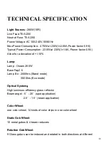
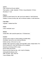
Page 10: ...actor 0 95 Allow for a deviation of 10 Lamp Lamp Osram 280W Base Fap2 5 Lamp life 2000hrs Stand mode 3000hrs Eco mode Optical System High luminous efficiency glass reflector Beam angel 5 20 spot application 2 5 10 beam application Color Wheel one color wheel 14 kinds of color chips in one color wheel Static Gob Wheel 10 metal gobos 4 beam reducers Rotation Gob Wheel 9 Glass gobos can be indexed an...

Page 11: ...r motorized zoom Strobe Strobe effect with variable speed max 15 flashes sec Control Graphic touch screen for fixture setting and addressing Gravitation sensor for auto screen positioning Battery backup of the touch screen Readout fixture and lamp usage receiving DMX values temperatures Etc Built in analyzer for easy fault finding error messages Remotely switching on off the lamp Built in demo seq...

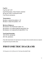
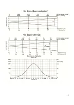
Page 12: ...tances Min distance from flammable surface 1m Min distance to lit objects Stand Mode 280W 10m Min distance to lit objects Eco Mode 230W 7 5m Total Heat Dissipation 1600 BTU h calculated 469 Wh calculated Please Note Specifications and improvements in the design of this unit and this manual are subject to change without any prior written notice PHOTOMETRIC DIAGRAMS All diagrams are for full power o...

Page 13: ...13 ...

Page 14: ...14 ...

Page 15: ...15 ...

Page 16: ...16 ...

Page 17: ...LR connectors Pin 1 GND Pin 2 Negative signal Pin 3 Positive signal Panel operation 1 Brief The light panel diagram show as Figure 1 Left area is TFT Displayer support touch and right area is encoder button both of touch and coder button can operate light and setting Display operation just like Android operation system touch the item will set or modify setting ...

Page 18: ...light setting parameters or view light state The area on the right hand side is rotary encoder with button As auxiliary input interface if disable touch function the encoder can been choose to set or view the item and then press the encoder button to confirm the selection rotary encoder again set the parameter value finally Press encoder button one again to save value or setting 2 Parameter value ...

Page 19: ... bottom of apply in the left corner to apply to the light but hav t saved Save Value Any time click on the lower right corner of the OK button the setting will been saved into internal memory 3 Boolean parameter setting when the selected parameters is a Boolean value such as ON or OFF can directly modify setting by chick corresponding item the setting will been saved right now When the parameter i...

Page 20: ...ect language TEST Used for test light modify DMX channel data to test function the corresponding function of reference channel function table ADVANCE Set light running parameter STATUS view light current status Figure 4 Parameter menu 3 Operation and parameter instruction Via following operation enter sub menu parameter menu shown in Figure 4 In main menu chick 1 6 function button into correspondi...

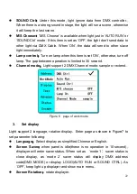
Page 21: ... right side of display will pop up diglog as in Fig 4 modify value then click ENTER to confirm and save DMX address code Figure 5 page of DMX Address 2 Set Light work mode Enter the page of WORK MOD as shown in Figure 6 and modify setting Can set light work mode control lamp and DMX channel mode Light includes 3 work mode DMX MODE AUTO RUN and SOUND MODE Parameter definition as following DMX Mode ...

Page 22: ...turn off lamp The gap between operation is limited to 30 second Channel mode Light support 2 DMX Channel mode sample or extend Figure 6 page of work mode 3 Set display Light support 2 language rotation display Enter page as shown in Figure7 to set parameter following Language Select display as simplified Chinese or English Screen Saver when panel is idle these is no operation in 10 second displaye...

Page 23: ... item Figure7 page of display 4 Test light Enter the page as shown in Figure 8 Light will into test mode in this mode the light does not receive the data for DMX controller PAN range for 0 to 255 TILT range for 0 to 255 FOCUS range for 0 to 255 COLOR range for 0 to 255 GOBO range for 0 to 255 PRISM range for 0 to 255 FROST range for 0 to 255 STROBE range for 0 to 255 ...

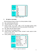
Page 24: ...fy enable set as OFF PAN or TILT will disable position rectify function As ON when PAN or TILT lose steps light will rectify auto Pan Offset Set PAN original position Tilt Offset Set TILT original position Lamp up when Select lamp on mode includes 3 mode power on after reset done and manual Factory setting restore all parameter to factory setting Figure 9 page of run parameter ...

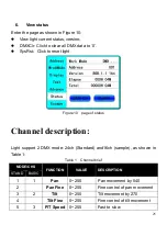
Page 25: ... of status Channel description Light support 2 DMX mode 24ch Standard and16ch sample as shown in Table 1 Table 1 Channel brief MODE CHS FUNCTION VALUE DESCRIPTION STAND BASIC 1 1 Pan 0 255 Pan movement by 540 2 Pan Fine 0 255 Fine control of pan movement 3 2 Tilt 0 255 Tilt movement by 270 4 Tilt Fine 0 255 Fine control of tilt movement 5 3 P T Speed 0 255 Fast to slow ...

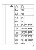
Page 26: ...Over 3 seconds 140 149 Reset Pan Tilt Over 3 seconds 150 189 Reset Effect motor Over 3 seconds 200 209 Reset All Over 3 seconds 210 229 none 230 239 Lamp Off Over 3 seconds 240 255 none 7 5 Color Linear color select 0 1 White 100 10 2 9 Color 1 100 10 10 19 Color 2 100 10 20 28 Color 3 100 10 29 37 Color 4 100 10 38 47 Color 5 100 10 48 55 Color 6 100 10 56 65 Color 7 100 10 66 74 Color 8 100 10 7...

Page 27: ...6 158 161 Color 7 162 166 Color 8 167 171 Color 9 172 176 Color 10 177 180 Color 11 181 185 Color 12 186 189 Color 13 190 215 Forwards rainbow effect from fast to slow 216 217 Stop white 218 243 Backwards rainbow effect from slow to fast 244 255 Auto color selection from fast to slow 8 Color Fine 0 255 Fine positioning 9 6 Effect Speed 0 255 Speed of Rotating gobo fast to slow 10 7 Static 0 3 Beam...

Page 28: ...hake Slow to fast 104 111 Gobo 3 Shake Slow to fast 112 119 Gobo 4 Shake Slow to fast 120 127 Gobo 5 Shake Slow to fast 128 135 Gobo 6 Shake Slow to fast 136 143 Gobo 7 Shake Slow to fast 144 151 Gobo 8 Shake Slow to fast 152 159 Gobo 9 Shake Slow to fast 160 167 Gobo 10 Shake Slow to fast 168 175 Gobo 11 Shake Slow to fast 176 183 Gobo 12 Shake Slow to fast 184 191 Gobo 13 Shake Slow to fast 192 ...

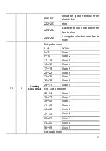
Page 29: ...ction from fast to slow 11 8 Rotating Gobo Wheel Rot gobo Index 0 4 White 5 7 Gobo 1 8 10 Gobo 2 11 13 Gobo 3 14 16 Gobo 4 17 19 Gobo 5 20 22 Gobo 6 23 25 Gobo 7 26 28 Gobo 8 29 31 Gobo 9 Rot Gobo rotation 32 34 Gobo 1 35 37 Gobo 2 38 40 Gobo 3 41 43 Gobo 4 44 46 Gobo 5 47 49 Gobo 6 50 52 Gobo 7 53 55 Gobo 8 56 59 Gobo 9 Rot gobo Index ...

Page 30: ...ion 130 137 Gobo 1 Shake slow to fast 138 145 Gobo 2 Shake slow to fast 146 153 Gobo 3 Shake slow to fast 154 161 Gobo 4 Shake slow to fast 162 169 Gobo 5 Shake slow to fast 170 177 Gobo 6 Shake slow to fast 178 185 Gobo 7 Shake slow to fast 186 193 Gobo 8 Shake slow to fast 194 199 Gobo 9 Shake slow to fast 200 201 White 202 221 Forwards gobo rainbow from slow to fast 222 223 stop 224 243 Backwar...

Page 31: ...otation 14 10 Prism 0 19 Open position hole 20 49 6 facet linear rotating prism indexing 50 75 6 facet linear rotating prism rotation 76 105 8 facet circular rotating prism Indexing 106 127 8 facet circular rotating prism rotation Prism Gobo macro 128 135 Macro 1 136 143 Macro 2 144 151 Macro 3 152 159 Macro 4 160 167 Macro 5 168 175 Macro 6 176 183 Macro 7 184 191 Macro 8 192 199 Macro 9 200 207 ...

Page 32: ...n 130 255 Backwards prism rotation from slow to fast 16 12 Frost 0 Open 1 179 Frost from 0 to 100 189 189 100 frost 190 211 Pulse closing from slow to fast 212 233 Pulse opening from slow to fast 234 255 Rambing from fast to slow 17 13 Zoom 0 255 Zoom from max to min beam angle 18 Zoom Fine 0 255 Fine Zoom 19 14 Focus 0 255 Continuous adjustment from far to near 20 Focus Fine 0 255 Fine Focus 21 0...

Page 33: ...t from slow to fast 224 255 Shutter open full lamp power 23 16 Dimmer 0 255 Dimmer intensity from 0 to 100 24 Reserved CLEANING AND MAINTENANCE Following are a few common problems that may occur during operation Here are some suggestions for easy troubleshooting CLEANING Frequent cleaning is recommended to insure proper function optimized light output and an extended life The frequency of cleaning...

Page 34: ...efer to the following points during routine inspections A detailed electric check by an approved electrical engineer every three months to make sure the circuit contacts are in good condition and prevent overheating Be sure all screws and fasteners are securely tightened at all times Lose screws may fall out during normal operation resulting in damage or injury as larger parts could fall Check for...

Reviews: