- -
11
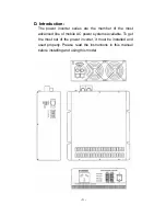
I-1. Controls and indicators:
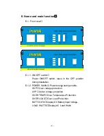
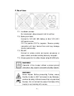
The ON/ OFF switch turns the control circuit in the power
inverter on and off. It does not disconnect power from the
power inverter. The inverter operates from an input
voltage ranging from:
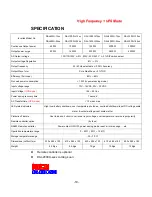
10 to 16 VDC for 12V models.
20 to 32 VDC for 24V models.
42 to 62 VDC for 48V models.
Peak performance for these inverter occurs when DC
input voltage is in the Range of 10 volts to 16 volts for
12V models and 20 volts to 32 volts for 24V models, and
42 volts to 62 volts for 48V models. From 600Watts up to
3000Watts.
l-2. Battery voltage indicator:
The battery voltage bar graph indicates the voltage at the
input terminals of the power inverter at low input current,
this voltage is very close to the battery voltage. At high
input current, this voltage will be lower than the battery
voltage because of the voltage drop across the cable and
connections. Ideally, the voltage should remain in the
green areas of the bar graph. If the voltage goes into the
red area at top and bottom of the graph, inverter may shut
down.
I-3. Load watt indicator:
The AC load watt bar graph indicates the power drawn
from the power inverter. It will indicate watt by loads. For
long term operation, the watt should in the green &
orange area of the bar graph. Short-term operation is
possible with watt in the red area. If the watt rises to the
flash all bar, the inverter will protect it-self.


