background image

ATV Portable Truck Scale Assembly Instructions                 

15

7.0

Assembly and Foundation Drawings

Figure 7-1. 70’ x 11’ ATV Assembly Drawing

Summary of Contents for SURVIVOR ATV series

Page 1: ...ATV Portable Truck Scale Assembly Instructions 68982...

Page 2: ......

Page 3: ...erview and Equipment Required 10 4 2 Trimming Individual Cells 10 4 3 Trimming Paired Sections 11 4 4 Calibrating with Test Weights 11 5 0 Load Cell Replacement 13 5 1 Replacement Procedure 13 5 2 End...

Page 4: ...ii ATV Portable Truck Scale Assembly Instructions...

Page 5: ...ss cables at each load cell metal conduit on weighbridge for load cell cable runs flexible conduit from load cell to metal conduit conduit fittings for flexible to metal conduit polycarbonate junction...

Page 6: ...complete wiring in approximately 1 2 hour Note these estimated times may vary 1 2 Recommended Equipment and Tools Crane maximum module weight is approximately 12 500 lbs Four chains or cables 8 minim...

Page 7: ...al Tag The serial tag on an ATV Series portable truck scale truck scale is found at the end of the scale near the SURVIVOR logo see Figure 1 3 A duplicate tag is placed inside of the J box pocket see...

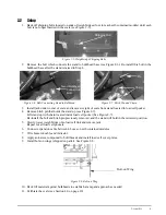
Page 8: ...Installation 3 Set other self contained module to other end of spacer tube spacer tube is used to ensure proper distance between self contained modules for installation of bridge module This module s...

Page 9: ...at holds the stand up see Figure 2 7 Lift stand up with chain located inside load cell pocket See Figure 2 7 Re install the bolt and hitch pin previously removed and the stand will hold in the retract...

Page 10: ...that holds stand in retracted position see Figure 2 9 3 Jack up each corner of module until hitch pin can be re installed in shipping position 4 Install bolt connecting stand to bulkhead base see Figu...

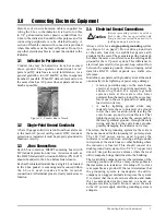
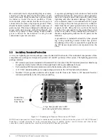
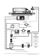
Page 11: ...ablish separate earth grounds for the scale These separate earth grounds do not share the same zero reference as the existing earth ground for the AC power system This difference in electrical potenti...

Page 12: ...ach the J box ground lug to the ground lug located in the J box pocket Grounding of the J box is essential for operation of the DC transient protection incorporated into the J box 3 5 Installing Trans...

Page 13: ...R16 R18 VR2 R19 R39 VR10 R35 R37 VR11 R27 R29 R31 R9 R11 R12 R1 R3 R5 VR5 R6 JP5 JMP NEG JMP POS VR8 VR3 VR1 VR12 VR6 J1 VR4 J2 R13 R7 EXPANSION J9 J5 ARC R46 JP4 JP3 ARGND JP14 JP15 JP13 L3 L4 L2 J8...

Page 14: ...the indicator Power up the indicator Turn all load cell potentiometers individual and section in the J box clockwise so all signals are at full strength Refer to the J box instruction manual for prop...

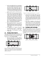
Page 15: ...s are trimmed for equal output pairs of load cells on opposite sides of the scale must be trimmed for equal sectional output This process is called section trimming 1 Park the loaded weight cart in th...

Page 16: ...he test weight truck bags of sand or any convenient items easy to load onto the scale This total calibration weight of 25 of scale capacity 12 5 test weights 12 5 substitution weight is required by we...

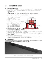
Page 17: ...all load cell and link assembly onto the baseplate Install load cell mount bolts and torque to 50 75 ft lb 7 Pull load cell cable through conduit using pull cord Make a loop in flex conduit between th...

Page 18: ...quipment by RLWS confirms that the non conformity actually exists and was not caused by accident misuse neglect alteration improper installation improper repair or improper testing RLWS shall be the s...

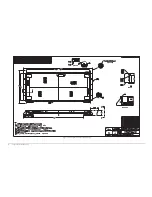
Page 19: ...ATV Portable Truck Scale Assembly Instructions 15 7 0 Assembly and Foundation Drawings Figure 7 1 70 x 11 ATV Assembly Drawing...

Page 20: ...16 Assembly and Foundation Drawings Figure 7 2 ATV Single Module 30 Assembly Drawing...

Page 21: ...ATV Portable Truck Scale Assembly Instructions 17 Figure 7 3 70 x 11 ATV Pier Foundation Print...

Page 22: ...18 Assembly and Foundation Drawings Figure 7 4 30 ATV Pier Foundation Print...

Reviews: