background image

Communications

© 

Rice Lake Weighing Systems


 All Rights Reserved

41

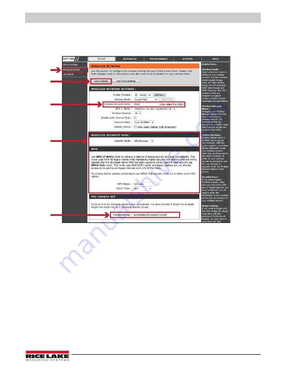
4.2.3 Setting Access Point (D-Link)

1. Execute browser and log in the setting page of access point.
2. Click 

WIRELESS SETUP

 on the left side of the setting page and enter into the AP settings page.

3. Click 

Save Settings

 button after the Wi-FI AP is completely set. After approximately 20 seconds, the setting of AP is 

stored and takes effect.

Summary of Contents for SST4

Page 1: ...SST4 Thermal Label Washdown Printer Technical Manual PN 212602 Rev A April 22 2022 ...

Page 2: ... respective companies All information contained within this publication is to the best of our knowledge complete and accurate at the time of publication Rice Lake Weighing Systems reserves the right to make changes to the technology features specifications and design of the equipment without notice The most current version of this publication software firmware and all other product updates can be ...

Page 3: ...ed at www ricelake com training or obtained by calling 715 234 9171 and asking for the training department Revision History This section tracks and describes the current and previous manual revisions for awareness of major updates and when the updates took place Revision Date Description A 4 22 2022 Initial manual release with the launch of the product Table i Revision Letter History ...

Page 4: ...tion 20 3 2 1 Getting Started 20 3 2 2 Keyboard Mode 22 3 2 3 Preview Label Function 23 3 3 LCD Interface Function 24 3 3 1 Main Menu Page 24 3 3 2 Device Page 25 3 3 3 Setting Items in Setting Mode 26 3 3 4 Status of LCD Interface 28 3 4 Label Calibration and Self Test 30 3 4 1 Label Calibration 30 3 4 2 Self Test 30 3 4 3 Label Calibration Button 31 4 0 Communications 32 4 1 NetSetting for Ether...

Page 5: ...allation 49 5 2 1 Heater Fuse Replacement 55 5 3 Wireless Antenna Kit 56 5 3 1 Prepare the Printer 56 5 3 2 Install the Antenna 57 6 0 Maintenance 63 6 1 Washdown Procedure 63 6 2 General Cleaning 64 6 3 Cleaning the Printhead 64 6 4 Print Line Adjustment 65 6 5 Ribbon Tension Adjustment 66 6 6 Thermal Printhead Cleaning 67 6 7 Balance and Printhead Tension Adjustment 68 6 8 Ribbon Shield Settings...

Page 6: ...T4 Washdown Printer iv Visit our website www RiceLake com Rice Lake continually offers web based video training on a growing selection of product related topics at no cost Visit www ricelake com webinars ...

Page 7: ...ntact any Rice Lake Weighing Systems dealer for replacement manuals WARNING Failure to heed could result in serious injury or death Do not use without the enclosure completely assembled and sealed Ensure power cord is disconnected from the power outlet before repairing or adjusting the product Product must sit on a level sturdy surface especially when the cover is open to prevent tipping Do not pl...

Page 8: ...own Enclosure Enclosure Clasp Transportation Handle this one used for opening enclosure Power Cord Ribbon rewind hub Ribbon supply hub Print mechanism Platen roller Release lever for print head Paper guide Label tension guide Label supply hub Label roll guide RFID module RFID module Adjustable sensor Paper guide Calibration button Ethernet port Serial port DB 9 USB port USB Host Power jack On Off ...

Page 9: ... of the unit using the back transportation handle 2 2 Interface Cable The SST4 can be interfaced to a host device via Ethernet Serial and USB ports Use the appropriate cable for application not included Ethernet Connection The Ethernet interface supports several menu selectable modes USB Connection The USB connection cable supports USB 2 0 Type B and USB Host Type A communications Serial Connectio...

Page 10: ...moving the nuts as they could slip and fall down between the plate and the printer enclosure Set the nuts aside Figure 2 2 Communications Cable Assembly 2 Pull the SST4 enclosure forward so that it hangs slightly off of table edge to allow access to the bottom access hole 3 Remove communications cable plates by pushing with fingers up through the bottom access hole from the underside to dislodge t...

Page 11: ... main plate is oriented correctly is to note that the four holes on the main plate have counter bores which should face down Figure 2 6 Incorrect and Correct Orientation of Main Plate 7 Pass the communications cable through the printer base and main plate Make sure that the cable end and printer communications socket match correctly Figure 2 7 Communications Cable Comes Up Through Bottom of Hole 8...

Page 12: ...ing the two pieces together Figure 2 8 Assemble Split Seal Plates Together 10 Place the O ring over the cable end and into the groove around the split seal plates Figure 2 8 right image This will hold the plates together and also offer a watertight barrier 11 Connect the communications plug to the appropriate connection on the back of the printer Figure 2 9 Connect Communications Cable to Back of ...

Page 13: ... half clamp plate onto the studs then place the clamp plate onto the studs with the step facing down and the half plate nesting in the step of the clamp plate Figure 2 12 Place Half Clamp Down on Assembly 15 Press the assembly down and partially tighten the four nuts that hold the entire assembly in place Once all the nuts are started tighten the nuts in a diagonal sequence until all the nuts are ...

Page 14: ...er printing TTP Requires a ribbon for transferring a printed image to a medium Direct thermal printing DTP Does not require a ribbon only thermal paper NOTE Check which printing method being used and alter the settings accordingly in the printer driver printer menu and or software 1 Turn printhead release lever counterclockwise to the top right position ...

Page 15: ...rd and fold it down 3 Place the label roll on the label supply hub pushing it right up to the printer frame IMPORTANT Do not apply too much pressure to avoid damaging the label stock NOTE When moving the label roll guide hold it only by the end that is attached to the bracket not by the top ...

Page 16: ... printer as shown in illustration below and pass it through the paper guide 5 Pass the label stock through the adjustable sensor and up to the tear off plate NOTE Remember to set the movable sensor to gap black mark or tag hole by changing the position of the sensor with the adjustment wheel ...

Page 17: ...etup Rice Lake Weighing Systems All Rights Reserved 11 6 The labels pass between the wall of the printer frame and the adjustable paper guide 7 Return the printhead release lever to its original position ...

Page 18: ...bbon supply hub 2 The two illustrations below show how to install the ribbon depending on the ribbon type ink side in or out 3 Pass the ribbon under the printhead and back up on the other side Attach it to the empty ribbon core on the ribbon rewind hub NOTE Do not pass the ribbon under the print sensor Ink Side Out Ink Side In ...

Page 19: ...able to the host computer 4 Switch on the printer The operator panel should light up 2 7 Installing Printer Driver and GoLabel 1 Insert the product CD in the CD DVD drive of the host computer and the program should pop up automatically The Welcome screen displays first On the Welcome screen choose Standard Installation The contents of the product CD can be downloaded from the SST4 product page at ...

Page 20: ...se Download the latest version from GoDEX server or Install from this product disc 4 As the printer driver and GoLabel are installing a screen displays a progress bar 5 Once the installation is complete make and print labels with GoLabel or through the printer driver ...

Page 21: ...s the files Installing Printer Driver Directly from CD Folder 1 Insert the product CD in the CD DVD drive of the host computer and open the Seagull Drivers folder on the product CD Select the icon for the driver file and click it to start the installation The contents of the product CD can be downloaded from the SST4 product page at www ricelake com 2 Follow the instructions on the screen The Driv...

Page 22: ...isit our website www RiceLake com 3 Specify the printer model 4 Specify the port used to connect the printer to the host computer 5 Enter a printer name and assign the appropriate rights Godex ZX1200i Godex ZX1200i Godex ZX1200i ...

Page 23: ... displayed Check whether the printer settings are correct and click Finish to start copying the driver files Wait until copying is complete then finish the installation 7 Once the driver installation is complete the new printer should appear in the Printers and Faxes folder Godex ZX1200i Godex ZX1200i Godex ZX1200i Godex ZX1200i ...

Page 24: ...rinter updates the Firmware automatically when plugged into the printer printer finds the Firmware in LABELDIR FW if it is a newer version Don t remove the USB memory stick while updating with Flash Writing message displaying on LCD panel USB Keyboard When plugging in a USB keyboard to the printer LCD touch panel displays Enter Standalone press the Y key on keyboard to enter the dialog for Keyboar...

Page 25: ...ia being used please see Section 3 4 on page 30 Pause Printing Pressing the FEED button while the printer is in standby mode to set the printer to pause mode In this mode the printer can receive commands but it only processes them when it is reset to standby mode Pressing the FEED button again resets the printer to standby mode Pressing the FEED button during printing interrupts printing When the ...

Page 26: ...nd the Start Up Screen appears If the printer is on Ready to Print status the LCD screen should display the message Ready on the screen Use the touchscreen to navigate the Home screen and other screens NOTE Tap the screen with a finger or a stylus pen to select on screen items such as settings icons Power On Wizard Test Main ZX1200i V2 100 2022 02 01 10 15 31 ...

Page 27: ...er Control Codepage Dump Mode Recall Label ZX1200i V2 100 2022 02 01 10 15 31 Tap Main Screen displays Main menu options 2022 02 01 10 15 31 ZX1200i V2 100 Wizard 0 Continuous 6 10 Darkness Speed Media Type 0 X Offset Y Offset Wizard Test Main Tap Wizard Screen displays printer setup parameters ZX1200i V2 100 2022 02 01 10 15 31 Wizard Test Main Test Self Test page Out of Dump Mode Tap Test Screen...

Page 28: ...LCD Language Printer Setting Label Setting Device Printer Control Codepage Dump Mode Recall Label Tap to save setting changes and return to the Main menu page Tap to return to the Main menu page without saving any changes Printer Settings Continuous Auto Select 6 10 Darkness Speed Sensor Select Media Type UNLOCK LOCK If printer functions locked printer can not receive any commands from GoLabel or ...

Page 29: ...menu page tap Recall Label to go to Recall Label page Preview Label Recall Label 001 002 FORM NAME LABEL 1 LABEL 2 0 0 0 Preview Label Recall Label 5 5 15 ZX1230i FW V2 000 Preview Label From the Recall Label page the touch panel shows all labels The Data processing time will be extend as long as the labels increase Tap UP to choose labels Tap DOWN to choose labels Tap Preview Label to see chosen ...

Page 30: ...er setting It consists of a table of values that describes the character set for a particular language Setting items for printing label ex Rotation Printing position offset Option modules and connection port settings Self Diagnose functions for printer ex TPH testing self test page printing Recall Label Dump Mode Table 3 1 Main Menu Page Items and Descriptions Main LCD Language Printer Setting Lab...

Page 31: ...osition Setting items for Serial Port e g Baud Rate Parity Data Bits Stop Bits Setting items for LAN e g Port NO DHCP Dynamic IP Default Gateway Subnet Mask Setting items for LCD e g Brightness Contrast Power Saving Password Setting items for Clock e g Year Month Day Hour Minute Table 3 2 Device Page Items and Descriptions Device Buzzer Option Setting Smart Backfeed Serial Port Setting LAN Setting...

Page 32: ... Reflective Media Type Label with Gaps Label with Marks Continuous Printing Mode Direct Thermal Thermal Transfer Tear off Position 0 40 Top of Form Apply Cancel LCD Language English Deutsch 繁體中文 簡體中文 Français Español 日本語 Italiano Pусский Türkçe Codepage 850 852 437 860 863 865 857 861 862 855 866 737 851 869 Win 1252 Win 1250 Win 1251 Win 1253 Win 1254 Win 1255 Win 1257 Table 3 3 Setting Item Deta...

Page 33: ... 4800 bps 9600 bps 19200 bps 38400 bps 57600 bps 115200 bps Parity Non Odd Even Data Bits 7 bits 8 bits Stop Bits 1 bits 2 bits LAN Setting DHCP On IP Address 0 0 0 0 Subnet Mask 255 255 255 0 Gateway 192 168 0 254 LCD Setting Brightness 5 Contrast 5 Power Savings 15 Password Off Clock Setting Year Month Day Hour Minute Printer Control Test Sample Pattern Select Memory Clear Memory Calibration Res...

Page 34: ...splayed in order to print Wizard Darkness 2 5 or 7 Speed 0 19 Media Type Label with Gaps Label with Marks Continuous X Offset Y Offset Bluetooth Clear Blind Enable Disable Make Device Visible Enable Disable SSP Enable Disable PIN Code 0000 Search Devices Test Self Test page Out of Dump Mode Item Details Table 3 3 Setting Item Details Continued ZX1200i V2 100 2022 02 01 10 15 31 Wizard Test Main ...

Page 35: ...scription To Upper Level Appears on the NAVIGATION ICON of Setting pages It guides back to upper level by touching display upper right icon To Main Menu Page Appears on the NAVIGATION ICON of Setting Value pages It guides back to Main menu page by touching display upper left icon Lock On Setting Value pages touch display icons to lock the value for preventing unexpected change Unlock Touch display...

Page 36: ...el Self Test Printout Contents Model Version USB ID setting Serial port setting MAC address of Ethernet port IP protocol setting IP address of Ethernet port Gateway setting Netmask setting Number of DRAM installed Image buffer size Number of forms Number of graphics Number of fonts Number of Asian fonts Number of Databases Number of Scalable fonts Free memory size Speed Density Ref Point Print dir...

Page 37: ...tartup or when changing a label or ribbon to another type such as a change from a gap label to continuous or black mark labels Press Calibration button for 2 seconds it uses auto sensing to calibrate the label and ribbon s parameters NOTE Press Calibration button is equivalent to the auto sensing command S SENSOR that cancels on printing job and make the Label Calibration immediately Press CALIBRA...

Page 38: ...duct page at www ricelake com To install NetSetting please follow these steps 1 Insert the product CD in the CD DVD drive of the host computer and open the Ethernet folder on the CD 2 Select the icon for the NetSetting installation file and click it to start the installation 3 Follow the instructions on the screen The Setup Wizard guides through the installation procedure 4 Specify the Installatio...

Page 39: ...fier icon to search the Godex printers which are connected via Ethernet port in the network environment Once a connected Godex printer is detected it will be listed on the start page There are six tabs at the top of the interface window which can configure different types of network settings The correct password is needed to enter the configuration pages for data security NOTE The default password...

Page 40: ... to either DHCP or Static IP Press Set button to apply the settings and Refresh button to refresh the setting values NOTE To fully benefit from the NetSetting software familiarity with basic networking principles is needed Please contact network administrator for related network setting information When enabling DHCP if the IP Address is IP 169 254 229 88 Netmask 255 255 0 0 Gateway invariable las...

Page 41: ...ted mail account when errors happened on the printer The alert messages are sent by SMTP Simple Mail Transfer Protocol or SNMP Simple Network Management Protocol Set or change the configurations of SMTP and SNMP on the Alert Path Setting tab Press Set button to apply the settings and Refresh button to refresh the setting values ...

Page 42: ...essage Setting For the alert message notification function decide which error cases need to be sent out to the operator The alert messages can be set to be sent by SMTP SNMP or both Press Set button to apply the settings and Refresh button to refresh the setting values ...

Page 43: ...ved 37 Printer Configuration Set or change the configurations of connected printer Most key settings for the printer operation can be done by settings on this page Press Set button to apply the settings and Refresh button to refresh the setting values ZX1200i ...

Page 44: ...the operator to control the printer Input printer commands in the Input Command window and press Send Command button to send commands to the printer For commands that return a response message the response message displays in Output Message window Press Set button to apply the settings and Refresh button to refresh the setting values ...

Page 45: ...be showed on the screen To update the printer firmware just specify the file location of the firmware file and press Start Download Firmware button The printer firmware then can be updated remotely In addition to updating the firmware the Recover To Factory Settings button can be pressed to restore the printer configurations back to factory default 227 L 9 ...

Page 46: ...4 2 2 Wi Fi Module Initial Setup 1 Power off the printer 2 Install the Wi Fi module NOTE Methods for installing Wi Fi module please refer to Wi Fi module installation 3 Power on the printer and wait 15 seconds The home screen displays a gray Wi Fi icon which means that the Wi Fi module is already detected by the printer NOTE The firmware version of the printer should be above V 2005 to use the Wi ...

Page 47: ... 1 Execute browser and log in the setting page of access point 2 Click WIRELESS SETUP on the left side of the setting page and enter into the AP settings page 3 Click Save Settings button after the Wi FI AP is completely set After approximately 20 seconds the setting of AP is stored and takes effect ...

Page 48: ...SST4 Washdown Printer 42 Visit our website www RiceLake com 4 2 4 How to Execute Wi Fi Tool 1 Execute GoLabel Version V1 12 2 Select ZX1200i printer model 3 Click Save 4 Execute the Wi Fi Tool ...

Page 49: ...on after the parameters are completely set Approximately 5 seconds later the printer will automatically reboot 3 Approximately 15 seconds LCD panel displays gray Wi Fi icon and it means that the Wi Fi module is already detected by the printer NOTE The Setting content of Wi Fi Tool should be corresponding with the setting of AP ZX1200i V2 100 2022 02 01 10 15 31 Wizard Test Main ...

Page 50: ...ated information of LAN ZX1200i V2 100 2022 02 01 10 15 31 ZX1200i V2 100 2022 02 01 10 15 31 Wizard Test Main Wizard Test Main ZX1200i V2 100 2022 02 01 10 15 31 Main LCD Language Printer Setting Label Setting Device Printer Control Codepage Dump Mode Recall Label Wizard Test Main Values may vary according to the actual situation Range of setting 500 65535 Device Buzzer Option Setting Smart Backf...

Page 51: ...1 Execute GoLabel Version V1 12 2 Select Printer Setup 3 Select Printer Interface and Click LAN Port and enter IP address 4 Click Save 5 Select Virtual Terminal and enter B into Command field and then click Send The Wi Fi connection is working if the printer returns related information automatically BOOT 2 005 F W ZX1600i V2 006 ...

Page 52: ... 111121 or 111872 Section 5 2 on page 49 Wi Fi Module Option Section 4 2 on page 40 Wireless Antenna Kit PN 113764 Section 5 3 on page 56 NOTE See Table 2 1 on page 3 for a list of all the SST4 printer variations and the options they each include The wireless antenna kit is included with SST4 Wi Fi option printers 5 1 Internal Rewind Option Use the following procedures for the internal rewind opti...

Page 53: ...whether the rewinder knob is in the closed position 3 Pull the liner back to rewinder shaft and rotate it 2 3 circles 4 Close TPH rotary arm The printer is ready to print NOTE With the rewind installed set the stop position in GoLabel E value and Driver to 6 Liner rewind can be operated without setting GoLabel and Driver Label Liner Rewind shaft ...

Page 54: ...d Roll Removal 1 Have the rewinder knob in the straight position 2 Pull the liner roll out NOTE The rewind is applied to liner only Do not use it with other printed labels If any adhesion is left on the label dispenser cover please clean it with soft fabric and denatured alcohol ...

Page 55: ...f condensation corrosion from condensation and low temperatures Thermostatically controlled the fan driven heater maintains a stable temperature within the enclosure to allow component parts to perform reliably over a longer period of time Whether installing the heater for the first time or replacing the unit there are several steps involved with the installation The heater kit should be mounted t...

Page 56: ...wing steps and photos to install or replace the heater 1 Unplug power to the unit 2 Disconnect any cables such as the power cord and the communications cable located on the back of the printer and the ribbon cable located at the front of the printer Figure 5 4 Disconnect Power and Printer Cables Hoffman heater fuse mounting bracket and wire harness Nut qty 1 Power cord ...

Page 57: ...r Base Plate 4 Gently pull the printer and printer pad off the printer base plate mounting studs and set aside The printer base plate is now exposed Figure 5 6 Pull Printer and Mounting Pad Off Base Plate 5 Remove the upper nut on the power cord cover Figure 5 7 Remove Upper Nut of the Power Cord Cover Assembly Use 3 8 socket to remove four nuts on printer pad Remove the nut from the power cord co...

Page 58: ... Clear Cover 7 Using a Phillips head screwdriver remove the three open terminal screws located on the terminal block Figure 5 9 Remove Open Terminal Screws 8 Set the heater into position onto the two threaded posts and using a 3 8 socket tighten up the nuts to secure the heater to the enclosure base NOTE The heater kit comes with one nut Use the second nut which comes from the upper left hand corn...

Page 59: ...l strip block as shown Figure 5 12 Connect Wiring Harness to Terminal Strip 11 Making sure the plastic spacers are in place put the clear plastic terminal strip cover on top of the terminal strip and using the 5 16 socket tighten the two nuts This should be done by hand to snug the nuts Over tightening can crack the clear plastic cover Figure 5 13 Replace Clear Plastic Cover and Gently Tighten BLK...

Page 60: ... the four metal studs Also ensure the ribbon cable at the front of the printer is also out of the way when placing the printer back into the enclosure Note the ground wire location leading to the front of the SST4 enclosure The wires should run between the side of the SST4 enclosure and the metal standoff This will eliminate the risk of wires being pinched Figure 5 15 Don t Pinch Ground Wire 14 Se...

Page 61: ...o replace the fuse 1 Using a slotted screwdriver push against the fuse holder cover and turn at the same time This will dislodge the fuse from the receptacle Figure 5 18 Push and Turn Fuse Receptacle to Remove 2 Pull the actual fuse from the receptacle and replace with a new fuse Figure 5 19 Remove Actual Fuse From the Receptacle and Replace with a New Fuse 3 Reverse the removal steps to re instal...

Page 62: ...ireless antenna option 2 Phillips head screwdriver 7 16 inch Socket 9 32 inch Socket 5 3 1 Prepare the Printer 1 Touch a bare metal part of the printer frame to dissipate any static electricity that may be present 2 Turn the printer off and unplug the power cable from the power outlet 3 Unlatch the SST4 hinges 4 Swing open the enclosure cover towards the front of the unit using the back transporta...

Page 63: ...ard so that it hangs slightly off of table edge to allow access to the bottom access hole 3 Remove communications cable plates by pushing with fingers up through the bottom access hole from the underside to dislodge the communications cable plates Catch bolts if they fall through Set aside Figure 5 21 Remove the Component Parts of the Communications Cable Assembly 4 The communications cable plate ...

Page 64: ...Loosen four screws on antenna assembly so the four bolts attached are loose and flexible yet attached to the plate Figure 5 24 Loosen Four Screws on Bottom of Antenna Assembly 7 Insert four loosened bolts on antenna kit through the printer base along with cable through the opening in the base Figure 5 25 Installing Antenna Kit Bolts and Cable Through Printer Base Bolts Screws ...

Page 65: ...plate have counter bores which should face down Refer to Figure 5 27 Figure 5 27 Incorrect and Correct Orientation of Main Plate 10 Push the entire SST4 enclosure unit back onto the table or other sturdy work surface 11 Assemble the split seal plates back together with the cable in between Figure 5 28 left image NOTE Run finger across the split seal plates to ensure there is no dirt or oil on the ...

Page 66: ...inter enclosure as shown below Figure 5 29 Seat the Split Seal Assembly 15 Wrap a small hole grommet that is included with the printer around the cable with the small end of the grommet pointing downwards Orient the grommet split to a position that is 90 degrees to the split in the split seal insert Press the grommet into the tapered hole in the split seal insert At this time position the cable as...

Page 67: ...nce all the nuts are started tighten the nuts in a diagonal sequence until all the nuts are tight using a 7 16 socket and torque wrench Tighten to 30 in lb torque Figure 5 32 Tighten Up The Entire Assembly 18 When tightening plates make certain to allow enough slack in cable Figure 5 33 Keep Proper Amount of Slack in Cable 19 Close and latch printer cover 20 Turn printer case on side to expose fou...

Page 68: ... Mounting Screws 22 Set printer on feet again Figure 5 35 Installed Wireless Antenna 23 Plug printer back in Open cover and turn on power 24 After printer display shows it is ready configure printer and devices to communicate with each other per the instructions provided in Section 4 0 on page 32 Four mounting screws Wireless Antenna ...

Page 69: ...6 1 Secure Main Latches 3 Ensure that the label presentation chute cover is securely closed The label cover tab will be tightened securely against retaining washer and mounting block Figure 6 2 Presentation Chute Location 4 Perform wash down 5 Dry the outside of the enclosure thoroughly before opening 6 Open the label presentation chute cover first to relieve any pressure or vacuum that might be p...

Page 70: ...ation or if poor quality paper has been used It is recommended that Rice Lake Weighing Systems supplied labels are used to obtain continuous high quality printing Recommended printhead cleaning intervals Due to abrasion and foreign particle deposits direct thermal printheads should be cleaned every 50 000 linear inches approximately eight rolls of labels 12700m Thermal transfer printheads should b...

Page 71: ...TPH module 2 Turn the printhead release lever counterclockwise to the top right position 3 If no improvement is visible turn the screws clockwise or counterclockwise as far as possible and be sure to align with the indicator board and indicator line Repeat the adjustment process until printing quality has improved indicator line indicator board ...

Page 72: ...bon supply hub To set the tension press in the knob and turn it clockwise or counterclockwise as required Increasing the tension of the ribbon rewind hub will remove any wrinkling of the ribbon during printing which results from the use of different ribbon materials For details about the wrinkling creasing of ribbons see Section 6 8 on page 69 If using a very narrow ribbon the printer may not move...

Page 73: ...sures a good print quality and a longer lifespan of the printhead Here is how to clean the printhead 1 Switch off the printer 2 Open the printer cover 3 Remove the ribbon 4 Release the printhead by turning the printhead release lever 5 To remove any label residue or other dirt from the printhead please use a soft lint free cloth dipped in alcohol to wipe NOTE The printhead should be cleaned once a...

Page 74: ... wrinkles the printhead pressure must be readjusted using the TPH spring boxes Move the TPH spring boxes as shown in the illustration to change the printhead pressure The wider the label being used the further apart the TPH spring boxes must be moved away from each other If there is no quality improvement change the pressure on the TPH spring boxes 3 Turning the screw left increases the pressure w...

Page 75: ...clockwise If the print result looks like the example in b turn ribbon shield screw counterclockwise To keep track of the change in print quality adjust the screws by half a turn at a time Print a test page If there is no improvement in the print result turn the screw by another half turn Do not turn the adjustment screw more than two full turns 360 NOTE If the screw is adjusted by more than two fu...

Page 76: ...tion 6 4 on page 65 There is no printed image on some parts of the label Check whether there is any label material or ribbon stuck to the thermal printhead Check for errors in the application software Check whether the starting position has been set correctly Check the ribbon for wrinkles There is no printed image on part of the label or the image is blurred Check the thermal printhead for dust or...

Page 77: ...solve the specific error Printhead Error 2 x 4 beeps The printing mechanism is not correctly closed Open the print mechanism and close it again Printhead Error None High temperature at the printhead Once the printhead has cooled down the printer switches to standby mode Media Error 2 x 3 beeps No ribbon is installed and the printer displays an error Make sure that the printer is set to direct ther...

Page 78: ...or black mark between the labels there is no paper Please reset the sensor File Error 2 x 2 beeps The memory is full The printer prints the message File System full Delete unnecessary data or install additional memory Unable to find file The printer prints the message File Name not found Use the X4 command to print all files Then check whether the files exist and whether the names are correct A fi...

Page 79: ...frame to dissipate any static electricity that may be present 2 Turn the printer off and unplug from the outlet 3 Unlatch the SST4 hinges 4 Unplug all cables that connect to the CPU board It is recommended to take a picture or label all connections before disconnecting them for ease of re installation 5 Unscrew the screws that attach the CPU board to the printer frame and slide the CPU board out R...

Page 80: ...o loosen the screw to take out the TPH module 2 Turn the printhead release lever counterclockwise to the top right position 3 Hold the printhead module pull out the TPH cable smoothly 4 Reverse order of previous steps to install TPH module NOTE Remember to switch off the printer before removing the printhead module ...

Page 81: ...ew belt since the other ends of the label wires travel inside of the drive belt 5 Reattach the belt containment gear wheel 6 Move the motor into position making sure the drive belt is positioned on the motor gear wheel closest to the printer frame and the internal rewind belt is positioned on the motor gear wheel closest to the motor 7 Start reinstalling the motor by first securing the right motor...

Page 82: ...onts Bitmap fonts 6 8 10 12 14 18 24 30 16X26 and OCR A B Bitmap fonts 90 180 270 rotating single characters 90 180 270 rotating Bitmap fonts 8 times expandable in horizontal and vertical directions TTF fonts TTF fonts Bold Italic Underline 0 90 180 270 rotating Download Fonts Bitmap fonts Bitmap fonts 90 180 270 rotating single characters 90 180 270 rotating Asian fonts 16x16 24x24 Traditional Ch...

Page 83: ...1253 1254 1255 1257 Unicode UTF8 UTF16BE UTF16LE Graphics Resident graphic file types are BMP and PCX other graphic formats are downloadable from the software Interfaces USB 2 0 B Type Serial port RS 232 DB 9 IEEE 802 3 10 100 Base Tx Ethernet port RJ 45 3 USB Host A type 2 ports at the front panel 1 port at the rear panel Control Panel Backlight 3 2 in touch screen LCD 1 Power on off button with ...

Page 84: ...SST4 Washdown Printer 78 Visit our website www RiceLake com ...

Page 85: ......

Page 86: ...WI 54868 USA U S 800 472 6703 Canada Mexico 800 321 6703 International 715 234 9171 Europe 31 0 26 472 1319 www ricelake com Rice Lake Weighing Systems Specifications subject to change without notice PN 212602 Rev A April 22 2022 ...

Reviews: