background image

Introduction

© 

Rice Lake Weighing Systems


 All Rights Reserved

1

1.0

Introduction

This manual is intended for use by service technicians responsible for installing and servicing RoughDeck

®

 LP floor scales. The 

RoughDeck LP floor scales are fully electronic, low-profile load receivers with a 2000 lb (907.20 kg) capacity. 

Manuals and additional resources are available from Rice Lake Weighing Systems at 

www.ricelake.com/manuals

Warranty information can be found on the website at 

www.ricelake.com/warranties

1.1 Safety

Safety Definitions:

DANGER: Indicates an imminently hazardous situation that, if not avoided, will result in death or serious injury. Includes 

hazards that are exposed when guards are removed.
WARNING: Indicates a potentially hazardous situation that, if not avoided, could result in serious injury or death. Includes 

hazards that are exposed when guards are removed.

  CAUTION: Indicates a potentially hazardous situation that, if not avoided, could result in minor or moderate injury.

IMPORTANT: Indicates information about procedures that, if not observed, could result in damage to equipment or 

corruption to and loss of data.

General Safety

Do not operate or work on this equipment unless this manual has been read and all instructions are understood. 

Failure to follow the instructions or heed the warnings could result in injury or death. Contact any Rice Lake 

Weighing Systems dealer for replacement manuals. 

  WARNING

Failure to heed could result in serious injury or death.

Before opening the unit, ensure the power cord is disconnected from the outlet. 
Do not allow minors (children) or inexperienced persons to operate this unit.
Do not operate without all shields and guards in place.
Do not jump on the scale.
Do not use for purposes other then weight taking.
Do not place fingers into slots or possible pinch points.
Do not use any load bearing component that is worn beyond 5% of the original dimension.
Do not use this product if any components are cracked.
Do not exceed the rated load limit of the unit.
Do not make alterations or modifications to the unit.
Do not remove or obscure warning labels.
Do not use near water. 
Do not lift scale without ensuring shoulder support screws (

Figure 2-1 on page 4

) are in installed in each corner (under load cell 

corner covers).

Summary of Contents for RoughDeck LP

Page 1: ...RoughDeck LP Low Profile Floor Scale Installation Manual PN 212616 Rev A April 29 2022...

Page 2: ...respective companies All information contained within this publication is to the best of our knowledge complete and accurate at the time of publication Rice Lake Weighing Systems reserves the right to...

Page 3: ...ates can be viewed at www ricelake com training or obtained by calling 715 234 9171 and asking for the training department Revision History This section tracks and describes the current and previous m...

Page 4: ...y 1 1 2 Scale Overview 2 1 3 Operating Requirements 2 1 3 1 Dimensions 3 2 0 Installation 4 2 1 Site Preparation 4 2 2 Unpacking 4 2 3 Floor Installation 5 2 4 Connecting Indicator Interface Cable 6 2...

Page 5: ...ures that if not observed could result in damage to equipment or corruption to and loss of data General Safety Do not operate or work on this equipment unless this manual has been read and all instruc...

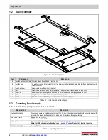
Page 6: ...ounted in a corner of the scale and rigidly fixed to the frame G Frame A rigid one piece welded unit that supports the scale system H Ramp A built in structure with 12 angle to aid in loading and load...

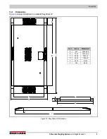
Page 7: ...ed 3 1 3 1 Dimensions Figure 1 2 displays dimensions for a standard RoughDeck LP Figure 1 2 RoughDeck LP Dimensions C B A D E Item Inches Millimeters A 9 00 2285 6 mm B 72 00 1828 8 mm C 90 25 2292 35...

Page 8: ...rushing cutting or moisture damage If necessary run the cable through conduit or other protection to prevent damage For proper operation the scale must be level within a 1 4 in 6 35 mm Choose a site w...

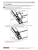
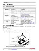
Page 9: ...ing 1 Remove the four Phillips machine screws securing the load cell cover to frame Retain screws for reuse 2 Pull the cover away from the frame to remove Figure 2 2 Load Cell Cover Retaining Screws 3...

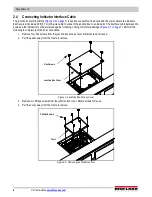
Page 10: ...e and the indicator must be protected against crushing cutting or moisture damage Figure 2 7 on page 7 Perform the following to complete junction box connections 1 Remove four hex screws from the junc...

Page 11: ...or correct wiring arrangement IMPORTANT If the site has potential dangers a method of protection is required such as running the cable in conduit or in a floor channel Figure 2 7 Interface Cable Prote...

Page 12: ...in junction box and reinstall six Phillips screws Figure 2 8 Removing Junction Box Cover 12 Reinstall the access cover with four hex screws IMPORTANT Ensure access cover installs flush with deck Figur...

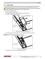
Page 13: ...ending or stripping threads if extended beyond the maximum height adjustment To adjust the scale perform the following 13 Place a level horizontally on the scale 14 Remove four Phillips machine screws...

Page 14: ...eight for RoughDeck LP models is 500 lb 226 80 kg 25 of 2000 lb 907 20 kg full scale 7 Ensure there is no weight on the scale and zero the indicator 8 Turn each of the four potentiometers clockwise to...

Page 15: ...ensure everything is seated 2 Ensure there is no load on the scale and place the indicator in the calibration mode 3 Perform a zero calibration 4 Place test weights equal to 70 80 of the scale capacit...

Page 16: ...indicator Install according to indicator installation manual Display stays at zero Indicator faulty Service indicator Load cell connections faulty Check cable connections in junction box and at indica...

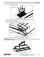
Page 17: ...frame to remove 7 Remove hex shoulder screw in corner Retain screw for reuse Figure 4 3 Load Cell Cover Retaining Screws 8 Attach eye bolts to 1 2 20 holes in deck corners and lift scale deck with cha...

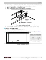
Page 18: ...12 Position the load cell near the corner where it will be installed 13 Route cable from load cell through the channels in the frame and to the junction box according to the wiring diagram in Figure 4...

Page 19: ...d Load Cup to Deck 18 Coil extra cable before it enters the junction box secure with cable ties and insert the coils into the channel IMPORTANT Do not cut load cell cables 19 Insert load cell cable th...

Page 20: ...e nuts must be tightened to the point where the rubber sleeving begins to protrude out of the nut 23 Pull each cable to ensure that they do not slip out of cord grip 24 Reinstall junction box cover wi...

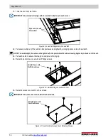
Page 21: ...support deck and frame Figure 4 12 Reattach Hex Shoulder Screw 27 Reinstall each load cell cover with four Phillips machine screws Figure 4 13 Reinstall Load Cell Cover 28 If required adjust load cup...

Page 22: ...mv v 350 Ohm NTEP III 5 M Alloy FM WW IP66 4 4 70212 Hex Bolt 0 50 20 x 1 75 x 1 25 N SST 8 5 31911 Concave Load Cup SST Hardened 4 6 18815 Ball 5 8 in DIA Chrome Plated Steel 4 7 208400 Shoulder Scre...

Page 23: ...07 20 kg Cable Length 20 ft 6 1 m for connecting junction box to indicator Threaded Eyebolt Two holes 1 2 20 NF Weighing Surface Dimensions W x L x H 36 in x 72 in x 1 81 in Scale Dimensions W x L x H...

Page 24: ...RoughDeck LP 20 Visit our website www RiceLake com...

Page 25: ......

Page 26: ...I 54868 USA U S 800 472 6703 Canada Mexico 800 321 6703 International 715 234 9171 Europe 31 0 26 472 1319 Rice Lake Weighing Systems Specifications subject to change without notice www ricelake com P...

Reviews: