background image

6

 Mechanical Chair Scale Installation and Operation Instructions


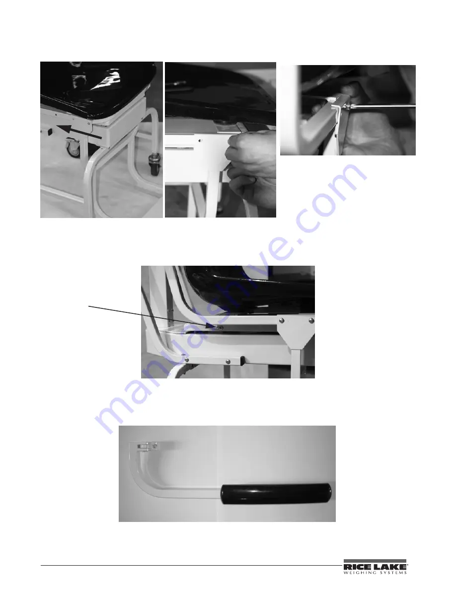
Push footrest assembly back 
so that the holes line up.

Figure 2-10. Slide the Footrest Assembly So That Holes Line Up

Once the footrest is secured and the screws tightened for it, secure the molded seat onto the chair scale 

frame.

6. Secure the four screws (shown below).

Secure screws (only one 
shown)

Figure 2-11. These Screws Hold The Molded Chair to the Scale Base

2.5

Arm Rest Installation

The last item to be installed on the mechanical chair scale are the two arm rests.

Figure 2-12. Detachable Arm Rest for the Mechanical Chair Scale

Use the following steps to attach the two arm rests to the mechanical chair scale molded seat.

Summary of Contents for RL-MCS

Page 1: ...111372 Rev A Rice Lake Mechanical Chair Scale Model RL MCS RL MCS 10 Operation Instructions...

Page 2: ......

Page 3: ...re Information 9 Chair Scale Limited Warranty 10 Technical training seminars are available through Rice Lake Weighing Systems Course descriptions and dates can be viewed at www ricelake com or obtaine...

Page 4: ...hanical Chair Scale Installation and Operation Instructions Rice Lake continually offers web based video training on a growing selection of product related topics at no cost Visit www ricelake com web...

Page 5: ...heels for easy portability The Rice Lake Mechanical Chair Scale comes in two models RL MCS lb kg 440 lb 200 kg capacity RL MCS 10 lb only 450 lb capacity Internet This manual can be viewed and downloa...

Page 6: ...shipping crate and lay out in a convenient place 2 1 Pillar and Beam Installation The pillar and beam comes separate from the scale base and must be attached prior to use Beam Pillar Figure 2 1 Pilla...

Page 7: ...d rod is located inside the pillar Remove the wire tie s holding the steelyard rod during shipment Insert the pillar into the base Once the pillar is inserted to the scale base the steelyard rod must...

Page 8: ...6 from the scale support frame and set aside The transport handle will attach to the scale support frame using those screws Transport handle Side screws x 4 Figure 2 6 Transport Handle Installation 2...

Page 9: ...ll also have to be put into place prior to tightening all screws 3 Remove screws from the chair frame shown in Figure 2 9 and set aside 4 Tilt the chair upwards as shown in Figure 2 9 This will allow...

Page 10: ...cure the molded seat onto the chair scale frame 6 Secure the four screws shown below Secure screws only one shown Figure 2 11 These Screws Hold The Molded Chair to the Scale Base 2 5 Arm Rest Installa...

Page 11: ...ole Location and Four Bolts Used for Securing Arm Rest to Chair 2 Secure the arm rests to the molded chair using the four bolts provided and shown in Figure 2 13 using the 5mm allen wrench that s been...

Page 12: ...sting Screw Location Lb Kg model shown 3 If the scale is not balancing properly then the small zero balance weight must be adjusted Turn the zero adjusting screw shown in Figure 3 1 using a flat head...

Page 13: ...ervice representatives are available 6 30 a m 6 30 p m Monday through Friday and 8 a m to 12 noon on Saturday CST Telephone Sales Technical Support 800 472 6703 Canadian and Mexican Customers 800 321...

Page 14: ...ll alleged non conformities Such equipment has not been modified altered or changed by any person other than RLWS or its duly authorized repair agents RLWS will have a reasonable time to repair or rep...

Page 15: ......

Page 16: ...ce Lake WI 54868 USA U S 800 472 6703 Canada Mexico 800 321 6703 International 715 234 9171 Europe 31 0 88 2349171 www ricelake com www ricelake mx www ricelake eu www ricelake co in m ricelake com PN...

Reviews: