


Communication
25
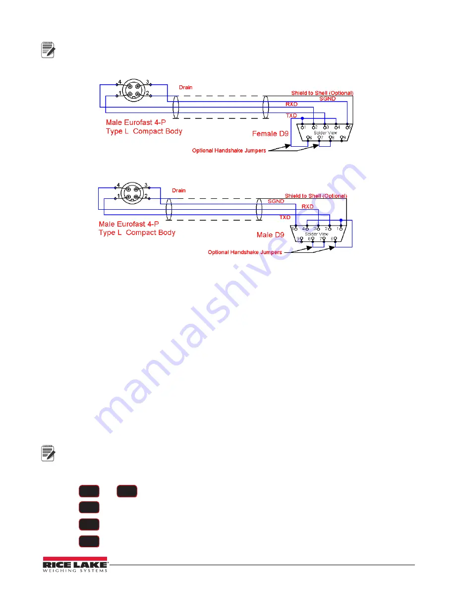
It may be necessary to disconnect the shield drain wire at the D-9 connector frame to prevent ground loops.
Ground loops can cause unstable readings. In extreme cases it may be necessary to use an opto-isolated
RS-232 interface.
Note
Figure 6-1. Serial Cable Schematic, DCE Configuration for
Connecting to a Computer
Figure 6-2. Serial Cable Schematic,
DTE Configuration for Connecting Directly to a DCE Printer
6.4 802.15.4 RF Network
When equipped with the 802.15.4 option, the
Dyna-Link 2
can connect with an
MSI-8000/8000HD
Remote
Display or an 802.15.4 modem. The unit uses three numbers to connect to an 802.15.4 piconet:
Note
•
ScaleCore ID
– uniquely identifies each ScaleCore device in a piconet. It has a range of 0-254 and must
not be duplicated within the same RF channel. For the
MSI-8000/8000HD
as network coordinator, Rice
Lake Weighing Systems recommends a number for the
Dyna-Link 2
from 0-3 if multiple units will be
connected to the
MSI-8000/8000HD
. If a single
Dyna-Link 2
is all that’s needed than any number up to 254
is acceptable.
•
RF Channel
– establishes the base network, all interconnected devices must match. This number must be
in the range of 12-23.
•
Network ID
– this is a 64-bit number that all interconnected devices must match. The
Dyna-Link 2
limits
this number to a max of 5 digits for a range of 0 - 99999. Do not use a small number here to help avoid
other 802.15.4 networks that default to a network ID of 0.
•
RF Strength
– transmission strength can be set from 0 to 4, default is 1. The settings effect the
transmission range with zero is lowest power level and four is the highest. Power 4 will use the battery life
quicker, so use the lowest number possible for reliable transmission. If maximum range is needed set the
strength to four.
For all devices that interconnect, the RF channel and network ID must match. The ScaleCore ID must be
unique. The Dyna-Link 2 or other MSI RF equipment that is a weight data source should be set to a
ScaleCore ID of 0, then if other slave devices are added, they can be added in sequence.
6.4.1
RF Network Setup
1. Press
and
simultaneously.
is displayed.
2. Press .
displays.
3. Press .
is displayed.
4. Press
to enter the ON/OFF setting.
F1
F2
F2
F1
F1


