background image

29

29

29

29

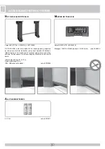
ASSEMBLY ACCESSORIES

G

B

P

AIR OF HALF-SHELLS

Utilized to mount JOLLY BIG motors on shafts of smaller diameter (76 
mm), also being previewed for advanced diameters (120 mm).
In nylon.
- Dim. = Ø 76 => Ø 102 mm                                         code ACJ9058

P

AIR OF PULLEY ADAPTER

Ø 240 => Ø 280 mm            

code ACJ9059

F

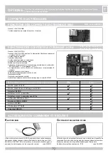
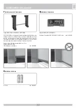
LAT STRONG BOX

Safety box preventing the access to controlling devices.
Supplied as a standard, with toggle switch (open-close) and electric brake 
release system.
Of die-cast aluminium - IP54.                                        code ACJ9071

K

EY SELECTORS 

Control for any type of automation.
Equipped with two microswitches with N.O. contacts of 15A 250V (Open/
Close) and one switch with N.C. contact of 4A 250V (Stop).
The selector can be opened only with the operating key. 
IP54     

- EMBEDDED WITHOUT STOP dim.: 100x100x109


 code ACG1010

- TO WALL WITHOUT STOP dim.: 100x100x42


 code ACG1030

F

LAT SURFACE MOUNTED PUSH BUTTON

OPEN/CLOSE

Control for any type of automation.
It is equipped with two microswitches with contacts 15A 250V.            
Dim.: 59,5x82,5x29                                                    code ACG2012

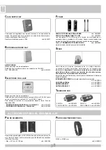
S

PARK

In  order  to  make  the  systems  mentioned  above  give  the  best 
performances,  you  need  to  install  an  antenna  tuned  on  the  frequency 
of the radio receiver installed. 

N.B. Pay attention to not let the central 

wire  of  the  cable  to  came  Into  contact  with  the  external  copper 
sheath, since this would prevent the antenna from working.

Install the antenna vertically and in such a way the remote control can 
reach it.

SPARK BLINKER WITH IN-BUILT INTERMITTENT CARD


code ACG7059

LATERAL SUPPORT


code ACG7042

SPARK ANTENNA 91


code ACG5454

SPARK ANTENNA 433


code ACG5452

F

IT SLIM

PAIR OF PHOTOCELLS

 for the wall-installation


code ACG8032

PAIR OF COLUMNS FOR FIT SLIM


code ACG8065

FIT  SLIM  photocells  have  synchronism  function  in  AC  current  and 
ranges of 20 m.
You can fit many photocell couples close together thanks to the optional 
synchronizing  circuit 

SYNCRO  TRANSMITTER  TX  SLIM  SYNCRO


code ACG8029 for more than 2 photocells couples (up to 4).

R

ADIO TRANSMITTER SUN

SUN 2CH 

code ACG6052 

SUN 4CH 

code ACG6054 

SUN CLONE 2CH  code ACG6056 

SUN CLONE 4CH  code ACG6058

Summary of Contents for JOLLY BIG ONE

Page 1: ... m2 280 kg 617 lbs OPERATORE REVERSIBILE CON FINECORSA AUTOMATICO PER SERRANDE AVVOLGIBILI BILANCIATE A MOLLE OPERATEUR REVERSIBLE AVEC REGLAGE FINE DE COURSE D AUTO ALIGNEMENT POUR RIDEAUX À ENROULEMENT EQUILIBRES PAR RESSORTS REVERSIBLE OPERATOR WITH REGULATION OF SELF REGISTERING RUN STOPS FOR ROLLING SHUTTERS BALANCED WITH SPRINGS OPERADOR REVERSIBLE CON REGULACIÓN DEL FINAL DE CARRERA REGULAD...

Page 2: ...eur supérieure à 50 mm de diamètre LA SOCIETE RIB N ACCEPTE AUCUNE RESPONSABILITE pour d éventuels dommages provoqués par la non observation dans l installation des normes de sécurité et des lois actuellement en vigueur ATTENZIONE PER LA SICUREZZA DELLE PERSONE È IMPORTANTE CHE VENGANO SEGUITE TUTTE LE ISTRUZIONI CONSERVARE CON CURA QUESTE ISTRUZIONI 1 Se non è previsto nel quadro elettronico inst...

Page 3: ...S INSTRUCCIONES CONSERVAR CUIDADOSAMENTE ESTAS INSTRUCCIONES 1 En el caso de que no sea previsto en la central eléctrica instalar antes de la misma un interruptor de tipo magnetotérmico omnipolar con una apertura mínima de los contactos de 3 mm que dé un sello de conformidad con las normas internacionales Este dispositivo tiene que estar protegido contro cierres accidentales por ejemplo instalándo...

Page 4: ...omatico C e D o E C e D o E C e D o E esempio tipico sono le chiusure che non accedono a pubblica via A Pulsante di comando a uomo presente cioè ad azione mantenuta come cod ACG2012 B Selettore a chiave a uomo presente come cod ACG1010 C Regolazione della forza per rispetto prova d impatto D Costole sensore di rilevamento ostacolo e o altri dispositivi di limitazione delle forze entro i limiti del...

Page 5: ... e serrarla insieme alle 2 La vite 3 NON DEVE fungere da vite antirotazione al posto della vite 4 E Rimontate la puleggia e riavvitate le sue due viti n 1 F Sull ultima sezione della serranda create un foro di Ø 12 mm che permetta di fissare la serranda alla puleggia del JOLLY BIG utilizzando la vite apposita n 5 G Inserite il cavo elettrico ed il cavo di sblocco nei fori sul palo ed eseguite i co...

Page 6: ... fornito dalla fabbrica C1 Finecorsa chiusura C2 Finecorsa apertura C1 e C2 devono trovarsi entrambi appoggiati contro i seeger S1 e S2 montati sulla vite del finecorsa L interruttore deve trovarsi in posizione INS Svitare il coperchietto del finecorsa con un cacciavite a croce piccolo Sguainate il cavo per 27 cm ed accorciate i 3 fili dell alimentazione a 4 cm Collegate il filo di terra giallo ve...

Page 7: ...eguire i collegamenti come da schema sottostante pulsante APRE con morsetto OPEN pulsante CHIUDE con morsetto CLOSE e al morsetto COM collegare la fase diretta dell alimentazione Riavvitate il coperchietto del finecorsa Verificare che l interruttore sia ancora su INS In questa fase i microinterruttori non funzionano e le camme dei finecorsa C1 e C2 vengono regolate automaticamente ...

Page 8: ...re a ridosso della sede del seeger S1 precedentemente tolto e con la camme C2 posizionata lontano dal seeger S2 Spostate l interruttore su DIS Ora i microinterruttori sono abilitati ad interrompere l alimentazione del motore quando vengono premuti alternativamente dalle camme C1 e C2 Eseguite un ciclo per verificare la bontà della regolazione MOLTO IMPORTANTE Togliere il seeger S2 Se le posizioni ...

Page 9: ...elettrica al motore Ogni due anni è consigliabile controllare il serraggio delle viti della puleggia e della vite di fissaggio al palo Controllare il corretto bilancimento delle molle e lubrificare la guida con del grasso siliconico MANUTENZIONE I Per poter eseguire in modo sicuro la movimentazione manuale della serranda occorre verificare che sulla serranda siano presenti maniglie idonee tali man...

Page 10: ...CCESSORI COLLEGABILI AI QUADRI ELETTRONICI Pulsantiera FLAT Pulsantiera con sblocco elettrofreno da parete Selettore BLOCK Selettore da parete da incasso Selettore da parete da incasso con Stop Cassaforti con pulsante e sblocco STONE e FLAT Radio trasmettitore 433MHz MOON Antenna 433MHz Fotocellule FIT SLIM Lampeggiatore SPARK MINI J CRX 4 4 4 4 4 4 4 4 4 4 4 4 4 4 4 Gestione 1 JOLLY BIG TWO Gesti...

Page 11: ...ne È dotata di due microswitches con contatti da 15A 250V Dim 59 5x82 5x29 cod ACG2012 SPARK Per ottenere le migliori prestazioni degli apparati sopracitati bisogna installare un antenna accordata sulla frequenza del radio ricevitore installato N B Fare molta attenzione che il filo centrale del cavo non vada a contatto con la calza in rame esterna ciò renderebbe nullo il funzionamento dell antenna...

Page 12: ...unzionano a batterie applicabile direttamente alla struttura mobile di porte sezionali e serrande avvolgibili Non è necessario quindi nessun collegamento filare alla centrale Portata segnale infrarosso selezionabile 5 m o 10 m Portata segnale radio 20 m IP54 Batterie non incluse cod ACG8048 Patent EP10706772 EP2345019 Gestisce 1 fotocellula NO TOUCH 868 12 30V ac dc cod ACG6154 2 X 3 6V cod ACG951...

Page 13: ... pour effectuer une manoeuvre manuelle Par conséquent il est obligatoire de refaire une compensation correcte du tablier Nous suggérons donc de repartir le poids du rideau sur un nombre approprié de ressorts libre interprétation ATTENTION La Norme EN 12445 Portes équipant les locaux industriels et commerciaux et les garages Sécurité à l utilisation del portes motorisées méthodes d essai au paragra...

Page 14: ...errée insérer la vis n 3 et la bloquer avec les n 2 La vis 3 ne doit pas fonctionner comme anti rotation au lieu de la vis 4 E Remonter la couronne et revisser ses deux vis n 1 F Sur la première lame du rideau créer un trou de Ø 12 mm qui permet de fixer le rideau à la couronne du JOLLY BIG en utilisant la vis appropriée n 5 G Insérer le câble électrique et le câble du déblocage dans les trous sur...

Page 15: ... seegers S1 et S2 montés sur la vis du fin de course L interrupteur doit se trouver en position INS Dévisser le couvercle du fin de course avec un petit tournevis cruciforme Retirer la gaine du câble de 27 cm et raccourcir les 3 fils de l alimentation à 4cm Connecter le fil de la terre jaune vert à la cosse fournie fixée sur le moteur Faire passer le fil de mise à la terre du câble d alimentation ...

Page 16: ...ON Exécuter les connexions selon le schéma ci après bouton OUVRE avec borne OPEN bouton FERME avec borne CLOSE et connecter la phase directe de l alimentation à la borne COM Revisser le couvercle du fin de course Vérifier que l interrupteur soit sur INS Dans cette phase les microcontacts ne fonctionnent pas et les cames des fins de course C1 et C2 sont réglées automatiquement ...

Page 17: ...ière du logement du seeger S1 précédentement enlevé et avec la came C2 positionnée loin du seeger S2 Déplacer l interrupteur sur DIS Maintenant les microcontacts sont habilités à interrompre l alimentation du moteur quand les cames C1 et C2 appuient alternativement dessus Exécuter un cycle pour vérifier que le réglage est correct TRÈS IMPORTANT Retirer le seeger S2 Si les positions de montée et de...

Page 18: ...vis de serrage à l arbre Contrôler le correct équilibrage des ressorts et graisser la coulisse avec de la graisse siliconée ENTRETIEN Pour pouvoir exécuter sûrement le mouvement manuel du rideau de fer il faut vérifier que il y ait des poignées appropriées sur le rideau de fer ces poignées soient placées de manière à ce qu elles ne créent pas de dangers durant leur utilisation leur force manuelle ...

Page 19: ...uction correspondants ACCESSOIRES RACCORDABLES AUX COFFRETS ÉLECTRONIQUES Bouton poussoir FLAT Bouton poussoir avec deblocage electrofrein Selecteur BLOCK Selecteur mural a encastrer Selecteur mural a encastrer avec Stop Coffres fort STONE et FLAT Émetteur 433MHz MOON Antenne 433MHz Photocellule FIT SLIM Clignotant SPARK MINI J CRX 4 4 4 4 4 4 4 4 4 4 4 4 4 4 4 Gestion 1 JOLLY BIG TWO Gestion 2 JO...

Page 20: ...ut type d automatisation Il est équipé de deux micro interrupteurs avec contacts de 15A 250V Dim 59 5x82 5x29 code ACG2012 SPARK Afin d optimaliser les performances des appareils suscités il est indispensable d installer une antenne accordée sur la fréquence du radiorécepteur installé N B Veiller à ce que le fil central du câble n entre pas en contact avec l enveloppe extérieure en cuivre dans le ...

Page 21: ...nent avec des batteries applicables directement à la structure des portes sectionelles et rideaux a enroulement Donc Il n y a pas besoin d aucune liaison avec des fils au coffret Portée signal infrarouges sélectionnable 5 m ou 10 m Portée signal radio 20 m IP54 Piles non incluses code ACG8048 Patent EP10706772 EP2345019 Il gère 1 PHOTOCELLULE NO TOUCH 868 12 30V ac dc code ACG6154 2 X 3 6V code AC...

Page 22: ... G B COMMAND TYPE USE OF THE SHUTTER Skilled persons Skilled persons Unrestricted use out of a public area public area with manned operation A B with visible impulses C or E C or E C and D or E e g sensor with not visible impulses C or E C and D or E C and D or E e g remote control device automatic C and D or E C and D or E C and D or E a typical example are those shutters which do not have access...

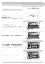
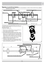
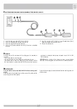
Page 23: ...s on the shaft as indicated on the rising above draw see pict 1 open the motor and mount it as indicated of continuation B Open the pulley unscrewing the 2 screws n 1 C Dismount the fixing flange on the shaft unscrewing the screws n 2 and n 3 D Mount JOLLY BIG on the shaft and position the motor up and the limit switch down see pict 3 Fit the Jolly BIG on the shaft by using the appropriate flange ...

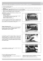
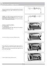
Page 24: ...against Seger rings S1 and S2 assembled on the screw of the run stop The switch must be in the INS position Unscrew the run stop cover using a small Philips screwdriver Strip the cable for 27 cm and shorten the 3 power supply wires to 4 cm Connect the yellow green earth wire to the fixed terminal provided on the motor Pass the earth wire of the motor power supply cable through the 1st free hole in...

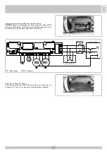
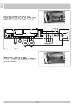
Page 25: ... provided CAUTION Make the connections according to the chart below OPEN button with OPEN clamp CLOSE button with CLOSE clamp and connect the direct phase of the power supply to the COM clamp Screw the run stop cover back on Verify that the switch is on INS In this phase the micro switches do not work and the C1 and C2 run stop cams are automatically regulated ...

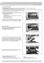
Page 26: ...removed and with cam C2 positioned away from Seger S2 Move the switch to DIS Now the micro switches are activated to interrupt the power supply of the motor when they are pressed alternatively by cams C1 and C2 Carry out a full cycle to verify correct regulation VERY IMPORTANT Remove Seger S2 If the positions of ascent and descent that are set need further modification this can be done directly de...

Page 27: ...the screws of the pulley and the screw fixing to the shaft are tighten Check that the springs are properly balanced and lubricate the guide with silicone grease MAINTENANCE To safely carry out the movement of the rolling gate it is important to verify that There are handles on the rolling gate Their position does not create dangerous points during the use The manual effort to move the rolling gate...

Page 28: ...ONECTABLE TO THE CONTROL PANEL FLAT Push Button Surface Push Button with Emergency Release BLOCK Key Selector Surface Embedded Key Selector Surface Embedded Key Selector w Stop Strong Box STONE and FLAT Radio Transmitter 433MHz MOON Aerial 433MHz Photocells FIT SLYM SPARK Light Yellow MINI J CRX 4 4 4 4 4 4 4 4 4 4 4 4 4 4 4 Control of 1 JOLLY BIG TWO Control of 2 JOLLY BIG ONE mounted on the same...

Page 29: ...switches with contacts 15A 250V Dim 59 5x82 5x29 code ACG2012 SPARK In order to make the systems mentioned above give the best performances you need to install an antenna tuned on the frequency of the radio receiver installed N B Pay attention to not let the central wire of the cable to came Into contact with the external copper sheath since this would prevent the antenna from working Install the ...

Page 30: ... and receiver operate with batteries fittable directly on the mobile part of sectional garage doors and rolling shutters For this reason It is not necessary any connection to the control board Infrared signal range 5 m to 10 m Radio signal range 20 m IP54 Batteries not included code ACG8048 Patent EP10706772 EP2345019 Manages 1 NO TOUCH 868 photocell 12 30V ac dc code ACG6154 2 X 3 6V code ACG9517...

Page 31: ...IÓN DEL CIERRE Personas expertas Personas expertas Uso ilimitado fuera del área publica área publica con hombre presente A B con impulsos a vista C o E C o E C y D o E ej sensor con impulsos fuera de vista C o E C y D o E C y D o E ej telemando automático C y D o E C y D o E C y D o E un ejemplo típico lo constituyen los cierres que no acceden a la vía publica A Pulsante de mando con hombre presen...

Page 32: ... 4 M10x50 está insertado en el agujero Ø 10 5 que actúa como bloque de la rotación del motor en el eje Despuès el aprieto del tornillo no 4 se insierte el tornillo no 3 y se apriete con el tornillo no 2 El tornillo 3 no tiene que trabajar como antirotación en lugar del tornillo 4 E Monte nuevamente la polea y apriete los dos tornillos no 1 F En la última sección de la puerta enrollable practique u...

Page 33: ...2 montados en los tornillos de final de carrera El interruptor tiene que encontrarse en posición de INS Destornillar la tapilla del final de carrera con un pequeño destornillador de estrella Esta instrucción es válida sólo si el operador se coloca en el palo en el cierre metálico con el motor dirigido hacia la derecha visto desde el interno del edificio Pelar el cable unos 27 cm y acortar los 3 ca...

Page 34: ...s conexiones como en el esquema de abajo pulsador ABRE con el borne OPEN pulsador CIERRA con el borne CLOSE y al borne COM conectar la fase directa de la alimentación Atornillar nuevamente la tapilla del final de carrera Controlar que el interruptor esté en INS En esta fase los microinterruptores no funcionan y las excéntricas de los finales de carrera C1 y C2 son reguladas automáticamente ...

Page 35: ...amente y con la excéntrica C2 posicionada lejos del seeger S2 Mover el interruptor a DIS Ahora los microinterruptores están habilitados para interrumpir la alimentación del motor cuando sean presionados alternativamente por las excéntricas C1 y C2 Ejecutar un ciclo para controlar la regulación MUY IMPORTANTE Quitar el seeger S2 Si la posición de subida y bajada programadas necesitan ulteriores var...

Page 36: ...olar cada dos años que los tornillos de la polea y el tornillo de fijación a la barra estén bien apretados Controle el equilibrio de los muelles y lubrique la guía con grasa de silicona MANTENIMIENTO Para efectuar el movimiento manual de la cancela en forma segura hay que controlar que Se provean manijas idóneas para la cancela Tales manijas no sean posicionadas en modo de crear puntos de peligro ...

Page 37: ...CCESORIOS ACOPLAMIENTABLES A LOS PANELES ELÈCTRICOS Botonera FLAT Botonera de Pared con desbloqueo electrofreno Selector BLOCK Selector de Pared de empotrar Selector de Pared de empotrar c stop Caja fuerte STONE y FLAT para Botonera c desbloqueo Telemando MOON 433MHz Antena 433MHz Fotocélula FIT SLYM Destellador SPARK MINI J CRX 4 4 4 4 4 4 4 4 4 4 4 4 4 4 4 Gestión 1 JOLLY BIG TWO Gestión 2 JOLLY...

Page 38: ... automatismo Dotada de dos microinterruptores con contactos de 15A 250V Dim 59 5x82 5x29 cód ACG2012 SPARK Para obtener las mejores prestaciones de los citados aparatos es necesario instalar una antena sintonizada con la frecuencia del radioreceptor Importante Controlar con atención que el hilo central del cable no esté en contacto con la protección de cobre externa Esto impediría el funcionamient...

Page 39: ...n baterias Las fotocelulas se pueden fijar directamente a la parte movil de las puertas seccionada o de las puertas enrollables No es por lo tanto necesario ninguna conexion de cables al cuadro de maniobra Alcance señal infrarroja seleccionable 5 m o 10 m Alcance señal radio 20 m IP54 Baterías no incluidas cód ACG8048 Patent EP10706772 EP2345019 Gestiona 1 fotocélula NO TOUCH 868 12 30V ac dc cód ...

Page 40: ...40 40 NOTES ...

Page 41: ...D 41 41 NOTES ...

Page 42: ...lación mantenimiento reparación y modificación realizadas y deberá conservarse para posibles inspecciones por parte de organismos autorizados MATERIALE INSTALLATO MATERIEL INSTALLEE INSTALLATION MATERIAL MATERIAL INSTALADO Data Date Date Fecha Descrizione dell intervento installazione avviamento verifica delle sicurezze riparazioni modifiche Description de l intervention installation mise en march...

Page 43: ...application de l art 6 paragraphe 2 de la Directive machines 2006 42 CEE et de ses modifications successives Sa mise en service est interdite avant que l installation ait été déclarée conforme aux dispositions prévues par la Directive This product can not work alone and was designed to be fitted into a system made up of various other elements Hence it falls within Article 6 Paragraph 2 of the EC D...

Page 44: ...am est 6 mm Cap Occh 5055 Fascetta L 98x2 5 Condensatore 20µF JOLLY BIG ONE Condensatore 40µF JOLLY BIG TWO Codice Denominazione Particolare Codice Denominazione Particolare CME2136 CME2139 CME2169 CMO1389 CPL1133 CPL1228 CTC1005 CTC1113 CTC1117 CTC1139 DAC29x19 DAC4x10 DAE55x16 DBO10x50Z Codice DDBM8 DDD8MA DDMM10 DRD4 DRL10x26 DRG10 DTB10x30 DTB8x30 DTE10x16 DTM10x140Z Cod CVA1816 04122013 Rev 1...

Reviews: