26
26
A
SSEMBLING THE NORMAL BARRIER
After having cemented the fixing base in the position you prefer, fix the
NORMAL unit, using the nuts supplied and a setscrew wrench n. 19.
Then fit the boom following the four steps below.
1 - Turn the release crank until you reach the stop in order to fit the boom in
the horizontal position (springs shall be under tension).
2 - Insert the boom hub in the bush you have fitted in one of the holes on
both sides of the column and then lock it to the reduction gear with the
screw TSPEI 10x90.
3 - Working from the ground, insert the U-plate on the boom with the four
screws M8x110.
4 - Fix the boom by using a n. 13 wrench to tighten the four M8x110 bolts to
the four nuts and then apply the plugs to its ends.
Afterwards, substitute the hexagonal plug of the superior portion of the
reduction gear unit with the plug supplied to release the oil pressure, by
using a setscrew wrench n. 24.
A
DJUSTING THE LIMIT SWITCHES
The barrier is normally supplied to you with its limit switches already
adjusted to allow an Ideal movement of the boom.
If the base plate has not been cemented correctly on level, the boom may
not be perfectly horizontal or vertical, therefore producing a poor aesthetic
result for the system. In order to avoid this, you can modify the mechanical
trajectory of the boom, adjusting the limit switches with two wrenches n. 9.
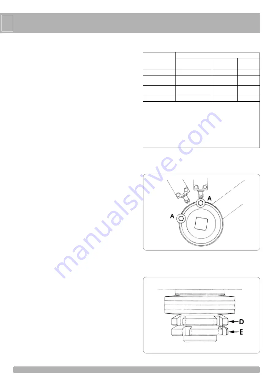
The electric limit switches can be adjusted, modifying the position of the
pawls A mounted on the disk. To do so, unloose the bolts that fix the pawls
to the disk with a setscrew wrench n. 10.
A
DJUSTING THE SAFETY CLUTCH
To adjust the safety clutch, use a ring nut wrench n. 30-32, release the ring
nut E and tighten the ring nut D clockwise, in order to increase the power
transmitted by the motor to the boom.
Make sure the boom stops and slightly resists movement when it comes
down. Block the ring nut E again when you have finished the adjustment.
INSTALLAZIONE NORMAL
2
3
GG
BB
COMMAND TYPE
USE OF THE SHUTTER
Skilled persons
Skilled persons
Unrestricted use
(out of public area*)
(public area)
with manned operation
A
B
with visible impulses
C
C
C and D
(e.g. sensor)
with not visible impulses
C
C and D
C and D
(e.g. remote controldevice)
automatic
C and D
C and D
C and D
* a typical example are those shutters which do not have access to any public way
A: Command button with manned operation (that is, operating as long as activated),
like code ACG2013
B: Key selector with manned operation, like code ACG1010
C: Safety edges, like code ACG3010 and/or other safety devices to keep thrust
force within the limits of EN12453 regulation - Appendix A.
D: Photocells, like code ACG8026
Parts to install meeting the EN 12453 standard


