


ASSEMBLY
F-4145 01/11
Assembly Section 3-3
© 2011 Alamo Group Inc.
ASSEMBL
Y
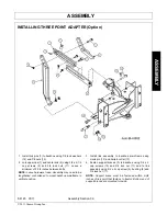
INSTALLING THREE POINT ADAPTER (Option)
1. Install link pins (7) to backhoe using 7/8 lock washers
(14) and 7/8 nuts (15).
2. Join upper link (1) and center link (2) using 3/4 x 2-1/2
cap screws (9) and 3/4 lock nuts (11). Leave a
minimum of 3-3/4 inches between bolts.
NOTE:
Leave hardware loose. Assembly may need to be
lengthened or shortened to mount backhoe mainframe in
vertical position.
3. Install link assembly to backhoe mainframe using
clevis pin (12) and hairpin cotter (13).
4. Fasten support braces (3) to backhoe using 3/4 x 2
cap screws (10) and 3/4 lock nut (11) and to link
assembly using 3/4 x 4 cap screw (9), bushing (5) and
3/4 lock nut (11).
NOTE:
Support brace must be fastened within 6-3/4
inches of link point that fastens to tractor. Bottom end of
support braces are mounted to inside
Summary of Contents for RHINO 95C
Page 5: ...Safety Section 1 1 SAFETY SECTION...
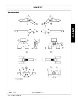
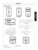
Page 19: ...SAFETY F 4145 01 11 Safety Section 1 15 2011 Alamo Group Inc SAFETY Decal Location...
Page 24: ......
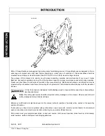
Page 25: ...Introduction Section 2 1 INTRODUCTION SECTION...
Page 28: ...INTRODUCTION F 4145 01 11 Introduction Section 2 4 2011 Alamo Group Inc INTRODUCTION...
Page 29: ...Assembly Section 3 1 ASSEMBLY SECTION...
Page 33: ...Operation Section 4 1 OPERATION SECTION...
Page 42: ......
Page 43: ...Maintenance Section 5 1 MAINTENANCE SECTION...
Page 50: ...MAINTENANCE F 4145 01 11 Maintenance Section 5 8 2011 Alamo Group Inc MAINTENANCE...
Page 53: ......