background image

SAFETY

F-4145   01/11

Safety Section 1-11

© 2011 Alamo Group Inc.

SAFETY

Transporting Safety Instructions and Practices

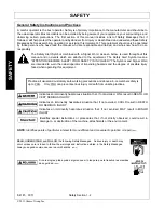
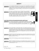
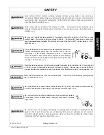
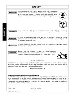
Transport only at speeds where you can maintain control of the equipment.
Serious accidents and injuries can result from operating this equipment at high
speeds. Understand the Tractor and Implement and how it handles before

transporting on streets and highways. Make sure the Tractor steering and brakes are in good
condition and operate properly.

Before transporting the Tractor and Implement, determine the proper transport speeds for you and
the equipment.  Make sure you abide by the following rules:

Test the tractor at a slow speed and increase the speed slowly.  Apply the Brakes smoothly to
determine the stopping characteristics of the Tractor and Implement.  As you increase the speed of
the Tractor the stopping distance increases.   Determine the maximum transport speed not to exceed
20 mph (30 kph) for transporting this equipment.

Test the equipment at a slow speed in turns.  Increase the speed through the turn only after you
determine that the equipment can be operated at a higher speed.  Use extreme care and reduce your
speed when turning sharply to prevent the tractor and implement from turning over. Determine the
maximum turning speed for you and this equipment before operating on roads or uneven ground.

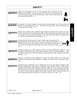
Only transport the Tractor and Implement at the speeds which allow you to properly control the
equipment.

Be aware of the operating conditions. Do not operate the Tractor with weak or faulty brakes or worn
tires.  When operating down a hill or on wet or rain slick roads, the braking distance increases: use
extreme care and reduce your speed.   When operating in traffic always use the Tractor’s flashing
warning lights and reduce your speed.   Be aware of traffic around you and watch out for the other
guy.    

(SG-19)

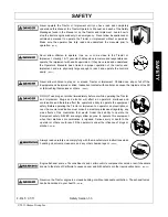
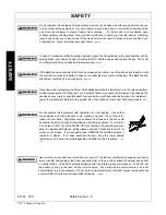
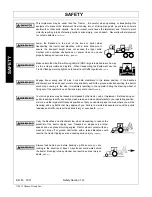
Be particularly careful when transporting the Implement with the Tractor.  Turn curves or go up hills
only at a low speed and using a gradual steering angle.  Rear mounted implements move the center of
gravity to the rear and remove weight from the front wheels.   Make certain, by adding front ballast, that

at least 20% of the tractor’s weight is on the front wheels to prevent rearing up,  loss of steering control or Tractor tip-over.
Slow down on rough or uneven surfaces to prevent  loss of steering control which could result in property damage or
possible injury. Dropping implement in transport can cause serious damage to the tractor and/or Implement and possibly
cause the operator or others to be injured or killed. 

 (SBH-38)

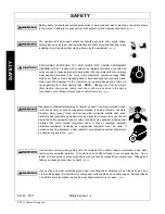
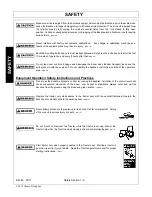
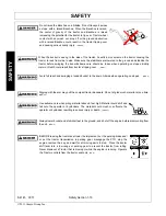
Do not drive near the edge of a ditch or excavation. The soil could giveway resulting in  loss of control
or rollover.  

(SBH-46)

Use extra care when turning or stopping. Allow for increased length and weight of added backhoe.
The backhoe adds five to six feet of length in rear of the tractor and significant weight. Allow extra
distance when stopping or turning. Do not allow backhoe or attachment to contact solid objects. 

(SBH-

16)

Summary of Contents for RHINO 95C

Page 1: ...L 60936 800 446 5158 Email parts servis rhino com BACKHOE This Operator s Manual is an integral part of the safe operation of this machine and must be maintained with the unit at all times READ UNDERS...

Page 2: ...n the implement and shown in your manual Observe the rules of safety and common sense WARRANTY INFORMATION Read and understand the complete Warranty Statement found in this Manual Fill out the Warrant...

Page 3: ...CKHOE TO TRACTOR 3 4 OPERATION SECTION 4 1 PRE OPERATION CHECKLIST 4 2 OPERATING DIRECTIONS 4 2 ENGINE SPEED 4 2 CONTROLS 4 2 BOOM SWING 4 2 CROWD BUCKET 4 2 LEFT HAND STABILIZER 4 3 RIGHT HAND STABIL...

Page 4: ...CATION 5 4 LUBRICATION CHART 5 4 HYDRAULIC TROUBLESHOOTING 5 5 VALVE SERVICE 5 7 MAIN RELIEF REPLACEMENT 5 7 SPOOL SEAL INSTALLATION 5 7 TORQUE SETTINGS 5 7 PARTS LIST 5 9 PROPER TORQUE FOR FASTENERS...

Page 5: ...Safety Section 1 1 SAFETY SECTION...

Page 6: ...re intended to warn the owner operator of impending hazards and the degree of possible injury faced when operating this equipment Indicates an imminently hazardous situation that if not avoided WILL r...

Page 7: ...ntrols can cause the Implement to shift or fall crushing themselves or others SG 25 DO NOT use drugs or alcohol immediately before or while operating the Tractor and Implement Drugs and alcohol will a...

Page 8: ...ut hope of natural recovery SG I7 Repeated or substantial breathing of hazardous dusts including crystalline silica could cause fatal or serious respiratory disease including silicosis Concrete masonr...

Page 9: ...ckhoe and the tractor while installing or disconnecting the Backhoe from the tractor Keep hands and body clear of the Backhoe and the Backhoe mounts Serious injury or death can result from a person be...

Page 10: ...ntrols Engage and disengage the boom and stabilizer transport locks and the swing lock pin with the engine off Do not operate the backhoe control from outside of the operator s area SBH 40 Do not use...

Page 11: ...from the backhoe resulting in serious injury to the bystander Position a barricade perimeter around the work area Stop operating the backhoe if any person enters the work area SBH 14 Prolonged operati...

Page 12: ...ulic failure may cause the implement to suddenly fall causing serious injury or possible death to anyone who might inadvertently be under the Implement Lower the implement carefully to the ground Do n...

Page 13: ...line remain in the tractor seat until the power has been shut off Stepping off the tractor can permit electrical current to pass through the body resulting in electrocution SBH 17 The Boom is designe...

Page 14: ...s tipping over SBH 1 Avoid full reach and swinging a loaded bucket to the down hill side when operating on slopes SBH 2 Digging with the arm may pull the compact tractor backward Do not dig too much...

Page 15: ...allow you to properly control the equipment Be aware of the operating conditions Do not operate the Tractor with weak or faulty brakes or worn tires When operating down a hill or on wet or rain slick...

Page 16: ...oe attachment such as a bucket were to drop suddenly and hit the ground while transporting the tractor could stop or swing to the side Immediately resulting in the operator hitting the steering wheel...

Page 17: ...ing in serious injury or death SBH 33 Perform service repairs and lubrication according to the maintenance section Ensure the unit is properly lubricated as specified in the lubrication schedule and a...

Page 18: ...Never work under the Implement the framework or any lifted component unless the Implement is securely supported or blocked up to prevent sudden or inadvertent falling which could cause serious injury...

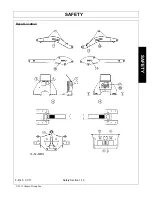
Page 19: ...SAFETY F 4145 01 11 Safety Section 1 15 2011 Alamo Group Inc SAFETY Decal Location...

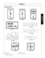
Page 20: ...DANGER Crushing Hazard 5 44895 2 DANGER Crushing Hazard 6 44900 1 OPERATION Left Side Stabilizer Position 7 44907 1 WARNING To Prevent Instability 8 44899 1 OPERATION Dipperstick Bucket Operation 9 44...

Page 21: ...SAFETY F 4145 01 11 Safety Section 1 17 2011 Alamo Group Inc SAFETY Decal Description 1 44901 6 44900 12 44909 13 44908 14 54288 15 54040 10 54287 8 44899 9 44898 16 54041...

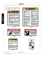
Page 22: ...Section 1 18 2011 Alamo Group Inc SAFETY 3 44896 2 45970 5 44895 4 44897 7 44907 11 48280 Note Safety decal location is listed below each decal Replace decal if damaged or illegible Replacement decals...

Page 23: ...ect the power source and wait for all machine movement to stop before servicing adjusting cleaning or unclogging the equipment except where the machine must be running to be properly serviced or maint...

Page 24: ......

Page 25: ...Introduction Section 2 1 INTRODUCTION SECTION...

Page 26: ...ns and information may be provided with your backhoe s sub frame or mounting kit or hydraulic kit That information should be kept with this manual at all times A Front End Loader or adequate front bal...

Page 27: ...Arc 180 E Transport Height maximum 95 66 F Transport Overhang 46 92 G Bucket Rotation 180 H Stabilizer Spread down position 90 I Stabilizer Spread up position 53 75 J Shipping Weight less bucket 1100...

Page 28: ...INTRODUCTION F 4145 01 11 Introduction Section 2 4 2011 Alamo Group Inc INTRODUCTION...

Page 29: ...Assembly Section 3 1 ASSEMBLY SECTION...

Page 30: ...tank port Point fitting up 4 Install filter body without filter element to 3 4 elbow 17 Be sure oil flow arrow on filter body is correct Position body so element points right Install filter element 7...

Page 31: ...ts NOTE Leave hardware loose Assembly may need to be lengthened or shortened to mount backhoe mainframe in vertical position 3 Install link assembly to backhoe mainframe using clevis pin 12 and hairpi...

Page 32: ...to upper connecting point on 3 point hitch using clevis pin and linch pin from 3 point hitch NOTE Insert adapter tube 5 in end of link assembly if necessary to adapt to smaller 3 point connecting pin...

Page 33: ...Operation Section 4 1 OPERATION SECTION...

Page 34: ...OLS The backhoe has two major control levers Boom Swing and Crowd Bucket These controls are located on the control panel directly ahead of the operator The stabilizer control levers are located betwee...

Page 35: ...h the controls Smooth light handling of controls will result in the most efficient backhoe operation Operate backhoe control levers to become familiar with their speed and movements Engine speed and P...

Page 36: ...bucket while starting to lift it from the excavation In this way excess material will fall back into the excavation DUMPING BUCKET To dump the bucket at the end of the digging cycle lift the bucket cl...

Page 37: ...Pile the soil on the opposite side of the trenches Position the unit forward with the lift and crowd levers so the two trenches can be connected Pile the spoil on the opposite side of the trench SIDE...

Page 38: ...tile Start the next trench using the spoil to fill the previous trench MISCELLANEOUS When finishing straight walls or bell holes in sandy soil use a platform under the rear tires and stabilizers The p...

Page 39: ...IMPORTANT Do not backfill by using the swing circuit and dragging the bucket sideways Doing so can cause damage to the dipstick boom swing cylinders or mainframe SEAT ADJUSTMENT To adjust seat up or d...

Page 40: ...porting backhoe 1 Completely raise stabilizers 2 Secure each stabilizer using stabilizer lock brackets TRANSPORTING THE BACKHOE CAUTION To avoid possible injury observe the following safety rules BEFO...

Page 41: ...tractor brakes 6 Lower backhoe by raising stabilizers and boom until backhoe or subframe rests on suitable blocking Leave stabilizers touching ground NOTE For added stability rest backhoe or subframe...

Page 42: ......

Page 43: ...Maintenance Section 5 1 MAINTENANCE SECTION...

Page 44: ...ll parts 7 Examine all parts for wear or damage and replace if necessary CYLINDER ASSEMBLY Note Be careful not to damage seals and o rings on edges or holes in cylinder tube Inspect and remove burrs a...

Page 45: ...hart Sharpen or replace worn bucket teeth Operate backhoe slowly for a short time before placing unit under full load Fully cycle backhoe through all movements several times to purge air from system H...

Page 46: ...of backhoe is dependent upon regular and proper lubrication of all moving parts with a quality lubricant All parts provided with grease fittings should be lubricated with a good quality chassis lube...

Page 47: ...lve 8 15 16 27 Sticky valve spool 16 19 20 21 Unable to push valve spool in 16 17 20 21 Spring centered spools do not return to neutral 16 17 18 19 20 21 POSSIBLE CAUSE CORRECTIVE ACTION 1 Low oil lev...

Page 48: ...tightened plug mounting bolt fitting or tie rod bolt See Item 30 17 Oil leakage past spool seal into spool cap If spool cap contains oil replace spool seal o ring If o ring retainer is bellied check...

Page 49: ...to 60 ft lbs SPOOL SEAL INSTALLATION 1 Remove the mechanical joystick kit from the top of the valve and the return kit from the bottom 2 Remove the old o rings and leave spool in housing making sure s...

Page 50: ...MAINTENANCE F 4145 01 11 Maintenance Section 5 8 2011 Alamo Group Inc MAINTENANCE...

Page 51: ...14 X 20 X 15 4 34 REGISTER 4 35 SPRING 4 36 PISTON 4 37 VALVE BODY RELIEF 4 38 O RING 17 17 X 1 78 4 39 O RING 1 40 PLUG 1 41 O RING 17 17 X 1 78 1 42 O RING 1 43 PLUG 6 44 SPRING 6 45 O RING 11 11 X...

Page 52: ...MAINTENANCE F 4145 01 11 Maintenance Section 5 10 2011 Alamo Group Inc MAINTENANCE PROPER TORQUE FOR FASTENERS...

Page 53: ......
Page 54: ...harges exceeding a reasonable amount as determined by Manufacturer and for returning the goods to the Dealer whether or not the claim is approved Purchaser is responsible for the transportation cost f...

Page 55: ...iently to confine the employee to the protected area provided by the ROPS REQUIRED OF THE OPERATOR 1 Securely fasten seat belt if the tractor has a ROPS 2 Where possible avoid operating the tractor ne...

Page 56: ...95C SOM 01 11 P N F 4145C Printed U S A...

Reviews: