45
11. Check to see that the high limit control is set above
the design temperature requirements of the sys-
tem.
For multiple zones: Check to make sure the flow is
adjusted as required in each zone.
12. Check that the heater is cycled with the thermo-
stat. Raise to the highest setting and verify that the
heater goes through the normal start-up cycle. Re-
duce to the lowest setting and verify that the heater
goes off.
13. Observe several operating cycles for proper oper-
ation.
14. Set the room thermostat or tankstat to desired
temperature.
15. Review all instructions shipped with this heater
with owner or maintenance person, return to enve-
lope and give to owner or place the instructions
inside front panel on heater.
OPERATION
Lighting Instructions
1. Before lighting, make sure you have read all of the
safety information in this manual.
2. Set the thermostat to the lowest setting.
3. Turn off all electrical power to the appliance.
4. This appliance is equipped with an ignition device
which automatically lights the burner. Do not try to
light the burner by hand.
5. Remove upper front panel.
6. Turn on main manual gas valve.
7. Wait 5 minutes to clear out any gas. Then smell
for gas, especially near the floor. If you then smell
gas,
STOP!
Follow the steps in the safety informa-
tion on the front cover of this manual. If you do not
smell gas, go to next step.
8. Turn on all electrical power to the appliance.
9. Set thermostat to desired setting. The appliance
will operate. The igniter will glow after the pre-
purge time delay (15 seconds). After igniter reach
-
es temperature (45 seconds) the main valve will
open. System will try for ignition three times. If
flame is not sensed, lockout will commence.
10. If the appliance will not operate, follow the instruc-
tions “To Turn Off Gas To Appliance,” and call your
service technician or gas supplier.
11. Replace access panel.
12. If heater fails to start, verify the following:
a. There are no loose connections or that the ser-
vice switch is off.
b. High temperature limit switch is set above wa-
ter temperature.
c. Thermostat is set above room temperature.
d. Gas is on at the meter and the heater.
e. Incoming gas pressure to the gas valve is NOT
less than 5.0 in. WC for natural gas, 11.0 in.
WC for propane gas.
To Turn Off Gas To Appliance
1. Set the thermostat to lowest setting.
2. Turn off all electrical power to the appliance if ser
-
vice is to be performed.
3. Remove upper front panels.
4. Turn off main manual gas valve.
5. Replace access panel.
Summary of Contents for Raypak Delta Limited 399B
Page 39: ...39 Wiring Diagram Models 399B 1259B...
Page 40: ...40 Wiring Diagram Models 1529B 2339B...
Page 51: ...51 DIAGNOSTIC DETAIL 12 J 7 J 6 J 5 J 3 0 2 0 16 S 1 F 2 F 3 F 4 F BLOWER DETAIL...
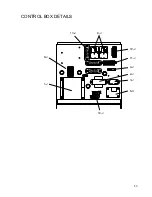
Page 53: ...53 13 J 8 J 10 J 11 J 4 J 2 J 3 J 6 C 14 J 9 J 1 J CONTROL BOX DETAILS...
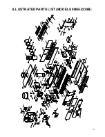
Page 57: ...57 ILLUSTRATED PARTS LIST MODELS 989B 2339B 10 J 3 O 5 O...
Page 58: ...58 12 H 6 H 7 H 8 H 2 H 9 H 3 H 5 H 1 H 4 H 1 P HEAT EXCHANGER DETAILS BURNER ASSEMBLY DETAILS...
Page 59: ...59 CONTROL BOX DETAILS 9 J 8 J 23 S 13 J 10 J 3 O 10 J 3 O 5 O FRONT SWITCH DETAILS...
Page 66: ...66...
Page 67: ...67 Raypak Inc 2151 Eastman Avenue Oxnard CA 93030 805 278 5300 Litho in U S A NOTES...


